
Sensors & PLC / Temperature Sensors
Is the Thermocouple, Extension Wire, or Input Card Causing the Wrong Temperature Reading?
- Doc
- thermocouple-reading-wrong-probe-wire-or-card
- Section
- sensors-plc/temperature-sensors
- Revised
A thermocouple loop produces one measurement from the probe, matching thermocouple or compensating extension cable, intermediate terminals, the input card and its cold-junction compensation (CJC), and the channel configuration. Replacing components one at a time can temporarily hide a poor connection or introduce a new dissimilar-metal junction, leading to a false diagnosis. The fastest method is a divide-and-isolate test: verify the downstream side with a known signal at the card terminals, then move the test boundary toward the field one section at a time. The conclusions in this article do not replace authorization to restart production or a calibration certificate.
Key Specifications
| Specification | Value | Source |
|---|---|---|
| Standard Thermocouple Types | The standard letter-designated thermocouple types are B, E, J, K, N, R, S, and T. Each type has a different alloy combination and temperature-EMF function. | NIST ITS-90 Thermocouple Database and NIST Monograph 175, https://its90.nist.gov/ |
| K-Type ITS-90 Reference Range | The NIST reference functions and tables cover -270 to 1372 °C. This is not the allowable operating range or guaranteed accuracy of a specific probe assembly. | NIST Monograph 175, Temperature-Electromotive Force Reference Functions and Tables, https://nvlpubs.nist.gov/nistpubs/Legacy/MONO/nistmonograph175.pdf |
| Cold-Junction Compensation | CJC must measure the terminal temperature to compensate for the effect of dissimilar-metal junctions at the input terminals. CJC error contributes to the total measurement error. | NI, Specifications Explained: C Series Modules, https://www.ni.com/en/support/documentation/supplemental/17/specifications-explained--c-series-modules.html |
| Effect of Open-Circuit Detection Current | Some input devices pass a small detection current through the circuit to detect an open. With long, small-gauge, high-resistance wiring, the current produces an additional voltage offset equal to the detection current multiplied by the loop resistance. | NI, Overview of Open Thermocouple Detection, https://www.ni.com/en/support/documentation/supplemental/10/overview-of-open-thermocouple-detection.html |
| Field Acceptance Criteria | There is no single universal limit. Determine the acceptance criteria from the combined specifications of the probe, extension wire, input card, CJC, and reference instrument together with the process tolerance. | NIST Thermocouple Calibration Services and the applicable input card and probe manufacturer specifications, https://www.nist.gov/pml/sensor-science/temperature-humidity/thermocouples-calibrations-services |
Types & Variations
Thermocouple Extension Wire (EXTENSION GRADE)
It is specified to have thermoelectric characteristics compatible with the applicable thermocouple and must be used with the correct type and polarity. Allowable temperature and tolerance class depend on the cable specification.
Use: Extend the run to the input device when field temperature and required accuracy remain within the selected extension-wire ratings
Compensating Cable (COMPENSATING CABLE)
It may not use the same alloys as the probe but imitates the thermoelectric characteristics of that thermocouple over a limited temperature range. Error can increase outside the specified type or temperature range.
Use: Use where permitted by the manufacturer and applicable standard, and where terminal-box and cable-route temperatures remain within the compensating-cable ratings
Dedicated Thermocouple Input Card
The card or terminal block performs thermocouple linearization, cold-junction compensation, and open-circuit detection.
Use: Connect the probe directly when the card supports the thermocouple type and input range
mV Input with External Compensation
The card reads voltage only; an external device or control logic performs CJC and type-specific linearization.
Use: Use in an existing system with verified and documented external reference-junction temperature measurement and conversion logic
Maintenance Steps
- 1. Preserve the Symptoms and Configuration
Capture the current displayed value, raw mV, thermocouple type, CJC method, open-circuit flag, filter, and scaling. Compare the configuration with a known-good channel, but do not change any values yet.Forcing or disconnecting a channel used for an interlock or alarm can disable protection. Establish an approved bypass procedure and dedicated watch, and confirm the LOTO scope.
- 2. Apply a Simulated Input at the Input Card Terminals
Identify and disconnect the field wires, then connect a thermocouple simulator configured for the same type in accordance with the card manufacturer wiring diagram. Apply one point near ambient and multiple well-separated points across the process operating range; record the display and raw values. Correct simulated values provisionally pass the card and scaling path. If the values are wrong, check the type configuration, CJC, terminal block, and channel.Adjacent power terminals inside the panel are separate hazards. Isolate power and verify absence of voltage. If energized diagnostics are unavoidable, follow site electrical safety procedures and use properly rated instruments and PPE.
- 3. Inspect the Extension Wire and Connections
Use the wiring diagram and conductor markings to trace type and polarity at both ends. Check for ordinary copper wire, terminals or connectors of the wrong type, loose connections, oxidation, moisture, crushing, and shield grounding at both ends. If necessary, disconnect both ends and test continuity and conductor-to-conductor and conductor-to-shield insulation to site requirements.Completely disconnect electronic equipment, including the card and transmitter, before insulation-resistance testing. The test voltage can damage connected equipment or become an ignition source in a hazardous area.
- 4. Compare the Probe Independently
Disconnect the probe from the extension wire and connect it directly to a portable indicator configured for the same type. Compare it with a reference instrument under stable process conditions or in an approved temperature source, and verify correct response during heating and cooling. If the value jumps when the probe or lead is moved, suspect an intermittent open in the head, leads, or junction.Before removing the probe from the process, use LOTO to isolate electrical, mechanical, thermal, and fluid energy and safely relieve residual pressure. Even with a thermowell, assess the possibility of leakage or breakage and stay clear of hot surfaces and discharge paths.
- 5. Verify the Complete Loop After Repair
Restore terminals to the specified torque and polarity, and update wire identification. Verify the entire loop at two or more test points in both rising and falling directions. Remove bypasses and forced values, then function-test alarms and interlocks.Remove LOTO and restart only in accordance with site procedures after approval from the equipment owner, confirmation that personnel and tools are clear, and restoration of all guards.
The Error Pattern Points to the Likely Cause
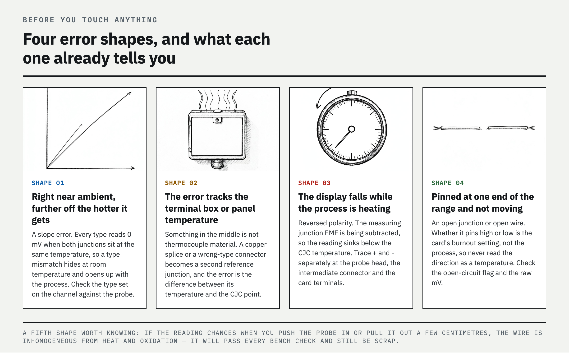
Before reaching for tools, observe how the reading is wrong. Each thermocouple-loop fault produces a different error pattern, and the pattern alone can narrow the cause to two or three candidates.
**The error increases proportionally with temperature but is small near room temperature** — This is a span or slope error. It occurs when the card channel is configured for a different thermocouple type than the installed probe. Every thermocouple type produces 0 mV when its reference and measuring junctions are at the same temperature, so the error is barely visible near room temperature. As process temperature rises, the reading diverges by the difference between the thermoelectric output curves. A K-type probe connected to a channel configured for J type is a typical example.
**The error changes with terminal-box or panel temperature** — This suggests that copper wire or a connector of the wrong thermocouple type has been introduced. If the extension section is not made of the correct thermocouple material, the connection becomes a new reference junction. The resulting error depends on the temperature difference between that junction and the card CJC location. This explains why the reading may be correct in the morning, when both locations happen to be at the same temperature, but become wrong after the panel warms during the day. The same pattern occurs when the CJC sensor is too far from the terminal block or the area around the terminals is locally heated.
**The indicated temperature falls while the process is heating** — The polarity is reversed. If + and - are swapped anywhere in the loop, the measuring-junction EMF is applied with the opposite polarity and the indicated value drops below the CJC temperature. Trace polarity at the probe head, intermediate connector, and card terminals.
**The reading is stuck at the upper or lower limit** — The junction or wiring is open. If the card open-circuit detection is configured upscale, the reading goes to maximum; if configured downscale, it goes to minimum. Because this direction is a card setting, do not infer the process condition from the direction alone.
**The reading changes when the probe is inserted or withdrawn a few centimeters** — The thermocouple wires may be degraded or inhomogeneous. High-temperature exposure and oxidation can change the alloy composition in a section of wire, producing an error only when that section lies within a temperature gradient. This fault can pass every room-temperature check, so the probe should be replaced.
Divide the Loop at the Input Card Terminals
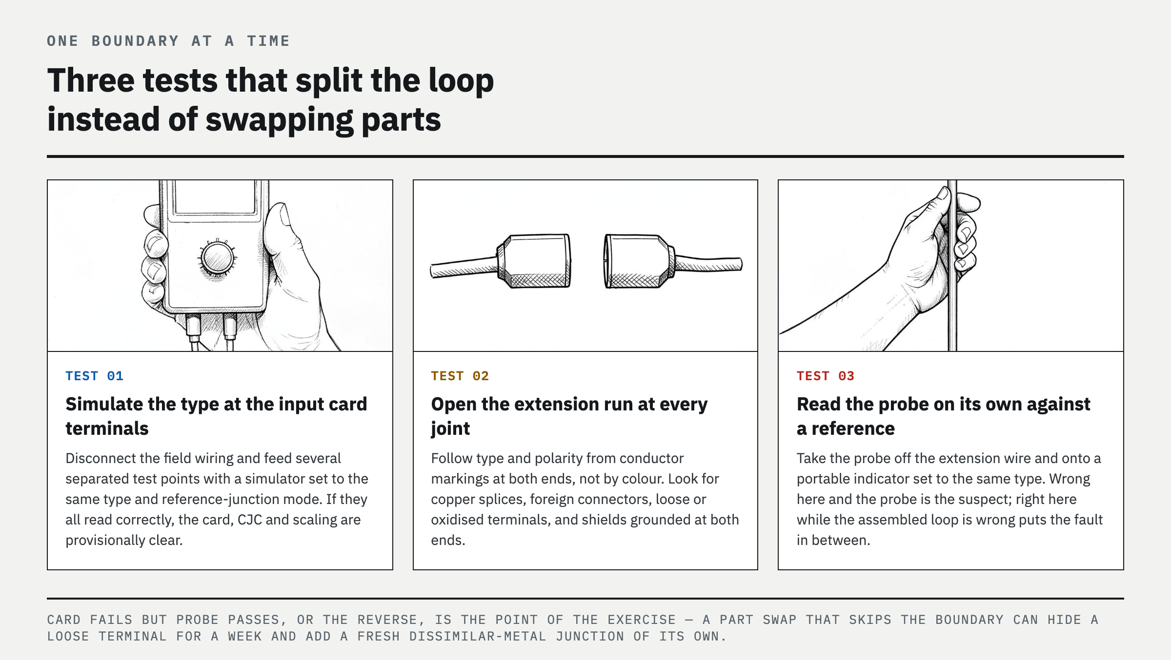
The only items needed are a thermocouple simulator that supports the target type, a portable thermocouple indicator or mV meter, a reference thermometer, the wiring diagram, and the channel configuration sheet. Before opening the panel or removing the probe, use lockout/tagout (LOTO) to isolate electrical, mechanical, thermal, and fluid energy and relieve residual pressure. Follow the maintenance sequence below from the card to the extension wire and then the probe. First record the displayed value, card raw value, alarm and open-circuit status, and differences from other channels. Connect the simulator at the input card terminals using the same thermocouple type and reference-junction conditions. If several test points read correctly, the card and downstream conversion path are generally good. Next, disconnect the probe from the field wiring, connect it directly to a portable indicator, and compare it with a stable reference temperature. If the card and probe each test correctly but the assembled loop does not, trace the extension-wire material, polarity, intermediate connectors, contact resistance, shielding, grounding, and noise.
Common Mistakes and Misdiagnoses
The most common mistake is determining polarity from wire color alone. Color codes vary by region and standard, so verify type and polarity from conductor markings and manufacturer documentation. Extending the circuit with ordinary copper wire or using a connector of another type creates additional thermoelectric junctions. The fault may remain hidden while both sides of the junction are at the same temperature, then shift with panel or terminal-box temperature. Reversing the two probe leads at the card can make the displayed value move opposite to process temperature or bias it toward ambient temperature.
Do not pass a probe based on resistance alone. A continuity test is useful for finding an open circuit, but it cannot reproduce the thermoelectric output of degraded alloy, insulation breakdown, ground loops, or intermittent opens. Conversely, on long, high-resistance wiring, the card open-circuit detection current can create an offset. A channel configured for J instead of K, a CJC sensor that does not accurately sense terminal-block temperature, or local heating near the card terminals can also look like a failed probe.
Verification and Final Diagnosis
After repair, verify both rising and falling response at a minimum of two different test points. Evaluate the differences among the card display, raw value, and portable reference instrument against the plant tolerance and the calibration uncertainty of each instrument. A single correct point at ambient temperature can conceal a type or polarity error. Close the terminal box, restore the actual wiring route, shielding, grounding, scan rate, and filter settings, and then verify the loop again.
Record the test signal, CJC method, thermocouple type, isolation boundary, measured values, ambient and terminal temperatures, and before-and-after readings. If the card fails the simulated-input test, move the signal to a known-good channel with the same configuration to distinguish a channel-specific fault from a common CJC or configuration problem. Classify a probe as defective after its failed direct test is reproduced in an approved reference temperature source or an insulation or physical defect is confirmed.
FAQ
How do I know if my thermocouple or input card is bad?
Apply several points with a simulator of the correct thermocouple type at the card terminals. If the values are correct, the card and downstream path are provisionally good. If the probe also reads correctly when connected directly to a portable indicator, the fault is in the extension wire, polarity, or connections between them. If the direct reading is wrong, suspect the probe. If the simulated input is wrong, cross-check the configuration, CJC, and channel against a known-good channel.
Can wrong thermocouple extension wire cause incorrect temperature?
Yes. Extension wire of the wrong type, ordinary copper wire, reversed polarity, or connectors made from other metals create additional thermoelectric junctions. The error may remain hidden while the junction temperature is stable, then shift as panel or terminal-box temperature changes. Trace type and polarity at both ends using conductor markings and manufacturer documentation.
Why does my thermocouple read room temperature?
Common causes are a short near the input terminals or an open probe junction when the card has no open-circuit detection or the function is disabled. Check the open-circuit flag and raw mV, then divide the loop with a simulated input at the card and a direct probe test. Use caution when interpreting a value produced by simply shorting the two probe terminals because it also reflects the card CJC condition.
Why is my thermocouple reading backwards?
First suspect reversed polarity. If the indicated temperature falls as the process heats or shifts toward ambient, trace + and - at the probe, extension wire, connectors, and card terminals. Do not rely on color alone; check the applicable standard and manufacturer conductor markings, and verify the thermocouple type configured in the card.
References
- NIST, ITS-90 Thermocouple Database
- NIST Monograph 175, Temperature-Electromotive Force Reference Functions and Tables for the Letter-Designated Thermocouple Types Based on the ITS-90
- NIST, Thermocouple Calibration Services
- NI, Specifications Explained: C Series Modules
- NI, Overview of Open Thermocouple Detection
Spotted an error or have a question about this guide? Email contact@fixtheplant.com — corrections are prioritized.