
Sensors & PLC / PLC I/O & Wiring
Why Does a PLC Input Stay On After the Sensor Turns Off?
- Doc
- plc-input-stuck-on-leakage-current
- Section
- sensors-plc/plc-io
- Revised
A digital input has no idea what a sensor is doing. It compares the voltage and current arriving at one terminal against two published limits and decides. So the fault is never really "the sensor did not turn off" — it is that something is still delivering enough current to keep that comparison on the wrong side of the line. Everything below works from that terminal outward.
Key Specifications
| Specification | Value | Source |
|---|---|---|
| OMRON CP1L normal input (CIO 0.10, 0.11, 1.00 to 1.11) | Input impedance 4.7 kΩ, input current 5 mA typical, ON voltage 14.4 VDC min., OFF voltage/current 1 mA max. at 5.0 VDC max. Anything between those two limits is undefined. | OMRON, CP1L CPU Unit Operation Manual (W471) — Section 2-2 Specifications, Input Specifications / Normal Inputs |
| EN 61131-2 Type 1 input, 24 V DC current sinking | Suitable for "3-wire sensors, mechanical switching contacts". Level 1 "HIGH" starts at 15 V; Level 0 "LOW" is listed as −3/15 (5) V. Poor match for two-wire sensors. | Beckhoff, Application Note DK9222-0909-0008 — Fig. 2, logic level for current sinking digital inputs (24 V DC), harmonised to EN 61131-2 |
| EN 61131-2 Type 2 and Type 3 inputs, 24 V DC current sinking | Type 2 is for "2-wire sensors, semiconductor technology"; Type 3 for "2-/3-wire sensors, reduced power consumption". Both take Level 1 "HIGH" from 11 V, and Level 0 "LOW" is listed as −3/11 (5) V. | Beckhoff, Application Note DK9222-0909-0008 — Fig. 2, logic level for current sinking digital inputs (24 V DC), harmonised to EN 61131-2 |
| Bleeder needed when sensor leakage exceeds module OFF current | Condition IOFF ≥ Ileak must hold. Otherwise R ≤ RIN × VOFF/(Ileak × RIN − VOFF), and Power W ≥ (VCC − VR)² / R × 4, where 4 is the stated allowable margin. | OMRON, CP1L CPU Unit Operation Manual (W471) — Section 3-4 Wiring, Precautions when Connecting a Two-wire DC Sensor |
| Worked example, CP1L normal input with a 1.7 mA leakage sensor | R ≤ 4.7 kΩ × 5.0 V / (1.7 mA × 4.7 kΩ − 5.0 V) = 7.9 kΩ, so use 6.8 kΩ. Power ≥ (24 V − 3 V)² / 6800 Ω × 4 = 0.26 W, so 0.5 W minimum and 1 W with thermal margin. | Calculated from the OMRON W471 equations and the W471 normal-input specifications above |
| Maximum current a two-wire sensor may draw under the standard | 30 mA, a figure the application note states is "adapted to the standard for 2-wire proximity limit switches, IEC 60947-5-2". A single channel at that draw is why Type 2 modules stay low density. | Beckhoff, Application Note DK9222-0909-0008 — why are there three types |
Types & Variations
Two-wire electronic sensor
One pair carries both supply and switched signal, so a residual current always flows while the output is off.
Use: Match its published leakage current against the input's OFF current before wiring, and prefer a Type 2 or Type 3 channel.
Three-wire PNP or NPN sensor
Separate supply and output conductors, but the output transistor still has its own specified off-state leakage.
Use: Confirm the sourcing or sinking polarity and the assigned common; a polarity mismatch produces a stuck indication that looks identical.
Dry contact through an interposing relay
A mechanical contact removes semiconductor leakage from the input entirely, at the cost of a component and a panel slot.
Use: Reach for this when the sensor and card cannot be matched, or when a lamp or suppressor across the contact is the actual leakage source.
Maintenance Steps
- Make the machine safe and capture the symptom
Follow the site energy-control procedure. Apply lockout/tagout (LOTO), isolate electrical and stored mechanical energy, bleed down pneumatic and hydraulic pressure, block gravity loads, and verify zero-energy state. Record the sensor LED, module LED, raw input tag, channel, terminal, and assigned common before moving a single wire.A PLC stop command is not energy isolation. Stored pressure, elevated tooling, charged capacitors, and remote starts can all still injure personnel.
- Measure input-to-common voltage and current
Energized diagnostics belong to a qualified person working under the facility's approved electrical-safe-work procedure. Use a properly rated meter and probes, take the reading at the input terminal against its own assigned common with the sensor on and off, and compare both numbers with the exact module data sheet limits.Do not move conductors or insert an ammeter in series on a live control circuit. De-energize first — an open meter lead can create an unexpected machine command.
- Lift the signal wire and divide the circuit
Reapply LOTO, prove de-energized, mark the conductor, and remove it from the input terminal. Secure the loose end. Under controlled power, observe whether the empty channel releases, then repeat the split at the nearest field junction box when the fault follows the cable.Restore guards, clear personnel, and control every restart. Never leave a loose conductor where it can touch supply voltage or another input.
- Fit and prove the correction
Repair the identified path, or install the calculated bleeder or interface relay. Check terminal seating and torque against the component instructions, cycle the sensor repeatedly, watch the raw input status, and retest at the low and high ends of the normal supply range and at operating temperature where practical.A bleeder dissipates heat continuously in one sensor state. Do not bury it in a wire duct, and do not choose wattage from resistance alone.
Read the terminal against the module's two published limits
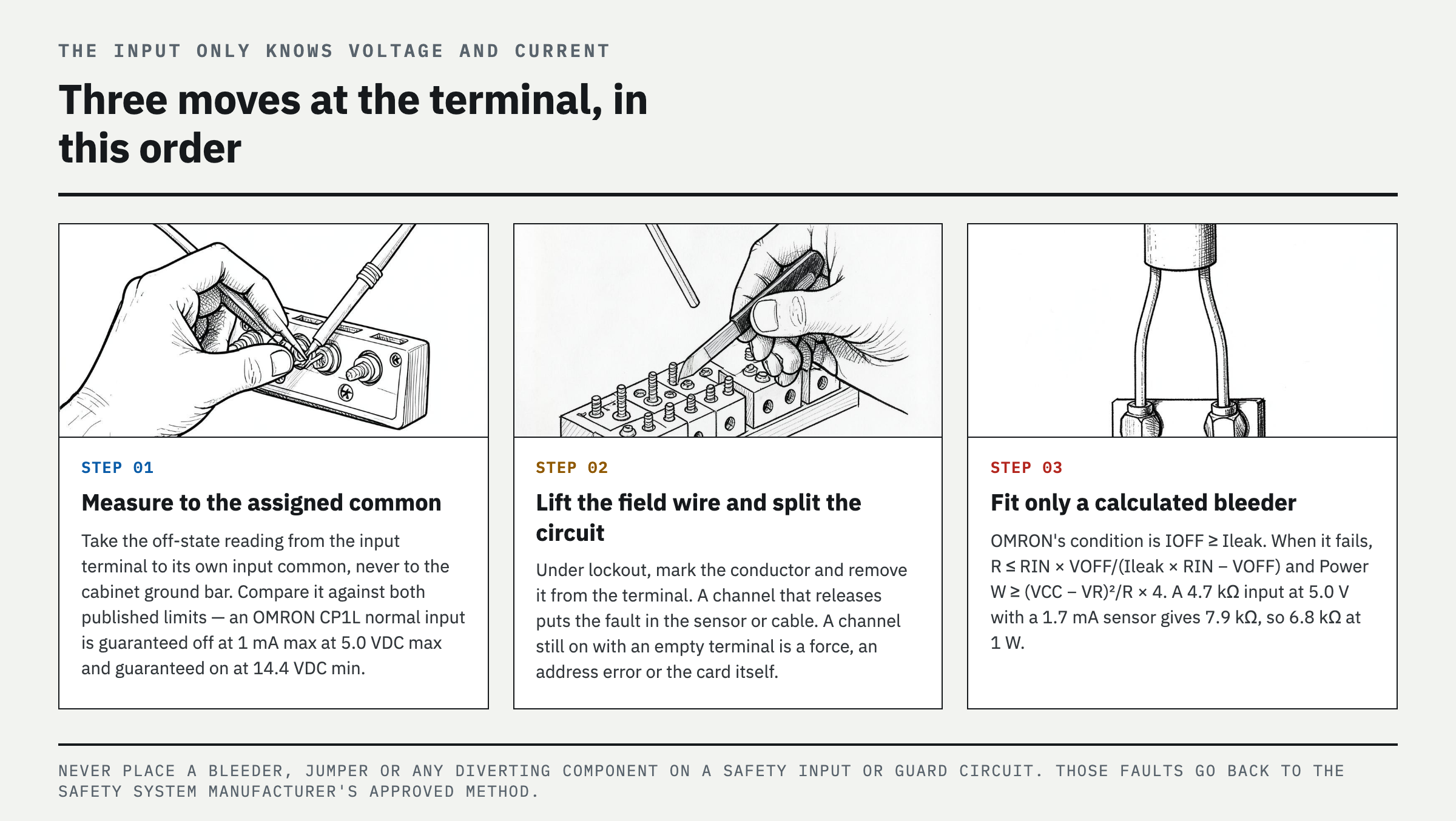
Put the meter from the suspect input terminal to its own assigned input common, never to the cabinet ground bar, and record the voltage with the target absent. Then compare that number against the module data sheet, which publishes two limits rather than one. An OMRON CP1L normal input is guaranteed OFF at 1 mA max at 5.0 VDC max, guaranteed ON at 14.4 VDC min, and has a 4.7 kΩ input impedance. Everything between 5.0 V and 14.4 V is undefined. That undefined band is where most stuck inputs actually sit. Voltage alone still does not close the case. A high-impedance meter reads coupled voltage on an open conductor carrying almost no current, and that ghost collapses the moment a real load is applied. Current is the honest measurement: residual voltage backed by more than the module's OFF current rating can hold the optocoupler, and a ghost cannot.
Check the input type before calling it a defect
EN 61131-2 defines three types of current-sinking digital input. Beckhoff's application note on the standard says of Type 1 that it "is therefore only suitable to a very limited extent or not at all for the use of 2-wire sensors, for which a high quiescent current is required." That one sentence resolves a large share of these calls. A two-wire proximity or photoelectric sensor draws current while off simply to power its own electronics, so the residual current is designed in rather than symptomatic. Type 2 was written for those sensors. Type 3 came later and carries the same quiescent current at lower power dissipation. Land a two-wire device on a Type 1 channel and nothing is broken — the pair was never compatible. The threshold gap looks small in print and decides the case in the panel. Type 1 does not treat the line as high until 15 V, while Types 2 and 3 do so from 11 V. Read the card's type from its own specification, not from the fact that it accepted 24 V.
Size the bleeder with the manufacturer's two equations
A bleeder resistor across the input diverts leakage so the terminal falls back into the guaranteed OFF window. OMRON publishes the sizing directly in the CP1L two-wire sensor precautions, and the trigger condition is a comparison, not a guess: connect one only when the sensor leakage current Ileak exceeds the module OFF current IOFF. Resistance comes from R ≤ RIN × VOFF/(Ileak × RIN − VOFF), and dissipation from Power W ≥ (VCC − VR)² / R × 4, where the 4 is OMRON's stated allowable margin. Work it with the CP1L numbers above and a sensor specified at 1.7 mA leakage: R ≤ 4.7 kΩ × 5.0 V / (1.7 mA × 4.7 kΩ − 5.0 V) gives 7.9 kΩ, so 6.8 kΩ is the next standard value down. Wattage then runs (24 V − 3 V)² / 6800 Ω × 4, about 0.26 W, which makes a 0.5 W part the floor and a 1 W part the sensible pick in a warm enclosure. Note where the heat goes: the resistor dissipates continuously in one sensor state, so it belongs on a terminal or bracket with air around it, never buried in a wire duct.
The cases a bleeder will not touch
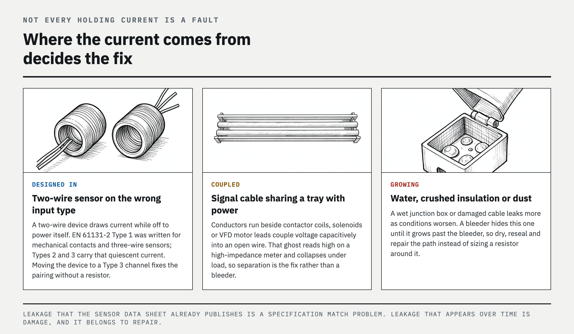
Resistance across the input is the right answer only for leakage that is supposed to be there. A wet or condensing junction box, crushed insulation, or conductive dust creates a path that grows as conditions worsen, and adding a bleeder hides it until it grows past the bleeder. Long signal conductors run in the same tray as contactor coils, solenoids, or VFD motor leads couple voltage capacitively into an open wire — that one is the classic ghost, and it usually disappears under load rather than needing a resistor. Then there is the group that has nothing to do with the field at all: a forced tag, a latched seal-in rung, a stale HMI screen, or a channel mapped to the wrong address. Lift the field conductor at the terminal under lockout, restore power under the site's controlled procedure, and watch the empty channel; an indication that stays on with nothing landed has already ruled the sensor and cable out. One firm exception overrides all of the above — never place a bleeder, jumper, or any diverting component on a safety input or guard circuit. Those faults go back to the safety system manufacturer's approved diagnostic method. OMRON's manual flags one more first-day trap worth knowing: sensor inrush at power-up can register as a false input before the sensor stabilises, and a short program timer after sensor power is the intended fix.
FAQ
Why does my PLC input show voltage when the proximity sensor is off?
Two-wire electronic sensors draw current while off to power themselves, and long parallel cable runs couple a small voltage into an open signal conductor. Measure from the input to its assigned common, then decide by current rather than voltage. A reading that collapses under load points to coupling; one that holds the input on has enough current behind it to need a circuit correction.
What resistor stops a PLC input from staying on because of leakage current?
No single value works everywhere. OMRON's CP1L manual gives R ≤ RIN × VOFF/(Ileak × RIN − VOFF) with Power W ≥ (VCC − VR)² / R × 4. Feed it the sensor's published leakage current, the module's input impedance and OFF limits, and the actual supply voltage. An interface relay or a Type 3 input card is the safer route when those figures are unavailable.
Can a bad PLC input card stay on with nothing connected?
Yes, though a software force, address mapping error, terminal debris, or shared-common wiring is more common. After LOTO and removal of the field wire, restore power under an approved test procedure. A channel whose module LED and raw tag both stay on with an empty terminal is a card-side or configuration problem, not sensor leakage.
Is a two-wire sensor on a Type 1 input actually broken?
Usually not. EN 61131-2 Type 1 was written for mechanical contacts and three-wire sensors, and the quiescent current a two-wire device needs can sit above what that input treats as off. Moving the device to a Type 2 or Type 3 channel fixes the pairing without a resistor.
References
- OMRON, CP1L CPU Unit Operation Manual (W471)
- Beckhoff, Application Note DK9222-0909-0008 — Digital inputs for 2-wire and 3-wire sensors according to EN 61131-2
- IEC, IEC 61131-2 Programmable controllers — Part 2: Equipment requirements and tests
- OSHA, The control of hazardous energy (lockout/tagout), 29 CFR 1910.147
Spotted an error or have a question about this guide? Email contact@fixtheplant.com — corrections are prioritized.