
Sensors & PLC / Proximity Sensors
Why Is My Proximity Sensor False Triggering Intermittently?
- Doc
- proximity-sensor-false-triggering
- Section
- sensors-plc/proximity-sensors
- Revised
This article covers industrial inductive, capacitive, and magnetic proximity sensors. Photoelectric and ultrasonic sensor issues involving reflections, ambient light, or crosstalk are outside its scope. Here, false triggering means that the output momentarily turns ON with no target present or chatters while detecting a stationary target. Intermittent false triggering often returns even after the sensor is replaced. Looking at whether the sensor actually switched, whether the output signal was corrupted in transit, and whether the PLC program created or stretched a pulse all at once can obscure the cause. The fastest approach is to place the sensor indicator LED, sensor-terminal output, PLC-terminal voltage, and raw PLC input bit on the same timeline and first isolate the fault boundary.
Key Specifications
| Specification | Value | Source |
|---|---|---|
| Sensor LED and raw PLC input change momentarily at the same time | First determine whether a target at the switching threshold, vibration, surrounding metal, contamination, mutual interference, or sensor-supply fluctuation caused an actual sensor transition. | OMRON, Proximity Sensors Technical Guide — sensing-method characteristics and selection considerations |
| Sensor LED remains stable, but only the raw PLC input changes | Investigate the connector, cable, common 0 V, input module, and program tag mapping downstream of the sensor. Compare the waveforms at the sensor and PLC terminals on the same timeline. | OMRON, Proximity Sensors Technical Guide — wiring and noise countermeasures |
| Output becomes stable when the target is moved closer to the sensor | Suspect insufficient sensing margin and the effects of target size or material, temperature, surrounding metal, and mounting position. Re-select using the model's assured sensing distance and standard target conditions. | Pepperl+Fuchs, Operating Distance as Central Characteristic; OMRON, Proximity Sensors Technical Guide — sensing distance and standard target |
| False triggering stops when one adjacent sensor is turned off or spacing is increased | Mutual interference is likely for the applicable sensing method, such as inductive sensing. Apply the model's minimum installation spacing and use the manufacturer's specified anti-interference function only on products that support it. | Pepperl+Fuchs, Installation Conditions for Inductive Sensors (TDOCT-6596) — Mutual interference; OMRON, E2B Instruction Sheet — Mutual interference |
| Occurs only when a motor, contactor, or solenoid operates | Measure voltage drop, common-mode shift, inductive or capacitive coupling, and coil surge separately. Do not alter cable routing, grounding, or shielding arbitrarily; follow each manufacturer's EMC guidance. | OMRON, Proximity Sensors Technical Guide — power, noise, and installation precautions |
Types & Variations
Inductive proximity sensor
Detects metal targets and is affected by target material and size, surrounding metal, mounting method, and electromagnetic mutual interference from adjacent sensors.
Use: Suitable for detecting the position of metal parts. Select shielded or unshielded construction, assured sensing distance, and installation spacing from the model datasheet.
Capacitive proximity sensor
Can detect resin, powder, and liquid as well as metal, so moisture, wall buildup, and changes in the sensitivity setting can cause false triggering.
Use: Used to detect nonmetallic targets or levels through a container wall. Verify sensitivity margin under both normal and worst-case contamination conditions.
Magnetic proximity sensor
Detects a magnet and is affected by strong nearby magnetic fields, changes in magnet position, and the orientation and strength of a cylinder piston magnet.
Use: Used for applications such as pneumatic-cylinder position sensing. Confirm cylinder and sensor compatibility and the mounting-slot position in the manufacturer's documentation.
Maintenance Steps
- Stop the equipment, support loads, and isolate energy
Stop shafts, cylinders, conveyors, and process fluids near the sensor in a safe position, and support gravity loads with rated blocking or supports. Identify and isolate electrical, pneumatic, hydraulic, mechanical, and thermal energy sources using the approved LOTO procedure.A stop button, PLC output OFF command, or removal of sensor power is not energy isolation. Physically prevent unexpected startup and load movement before reaching inside a guard or adjusting the sensor position.
- Dissipate stored energy and verify a zero-energy state
Release residual pressure from pneumatic and hydraulic circuits and accumulators through the designated discharge path, and dissipate or restrain spring, gravity, and rotating energy. Verify absence of voltage and inability to restart using approved instruments and site procedures.Even when a pressure gauge reads zero, pressure may remain trapped behind a check valve or inside a cylinder chamber. Do not loosen a fitting to release residual pressure.
- Clean and inspect fastening and installation conditions
Remove chips, oil, and moisture from the sensing face using methods compatible with the product material, and inspect the sensor body, bracket, target, connector, and cable for damage. Set tightening torque, metal clearance, and sensor spacing according to the model manual.Do not touch a plastic sensing face with a metal tool or clean it with a solvent not approved by the manufacturer. Overtightening a threaded sensor can damage its housing and internal circuitry.
- Perform a controlled energized test and isolate the signal boundary
With power off, connect probes to isolated test points and guard exposed conductors. Remove tools and materials, restore guards and protective devices, clear personnel from the test area, and restore energy under the approved test procedure. Record the sensor LED, sensor-terminal output, PLC-terminal voltage, raw PLC input, and interference-source timing simultaneously. After the test, de-energize the equipment again and reapply energy controls before continuing work.Energized measurements must be performed by a qualified person using CAT- and voltage-rated instruments and isolated or differential probes suitable for the circuit and environment. U.S. facilities must follow OSHA 29 CFR 1910.147(f)(1); facilities in other jurisdictions must follow local regulations and site procedures. Do not shake a sensor or cable by hand inside a hazardous area while equipment is operating.
- Verify the correction under worst-case conditions
Correct one cause at a time and repeat the test at the minimum and maximum expected speeds, target tolerances, temperature, contamination levels, and surrounding-equipment startup conditions. Confirm that both the raw-input pulse record and the process result remain stable, then save reference values and installation photographs in the maintenance history.Do not arbitrarily extend the response time of a safety-related signal with a PLC input filter. Verify the safety function separately according to the safety circuit's validation procedure and required performance.
Confirm the symptom — do the sensor LED and PLC input change together?
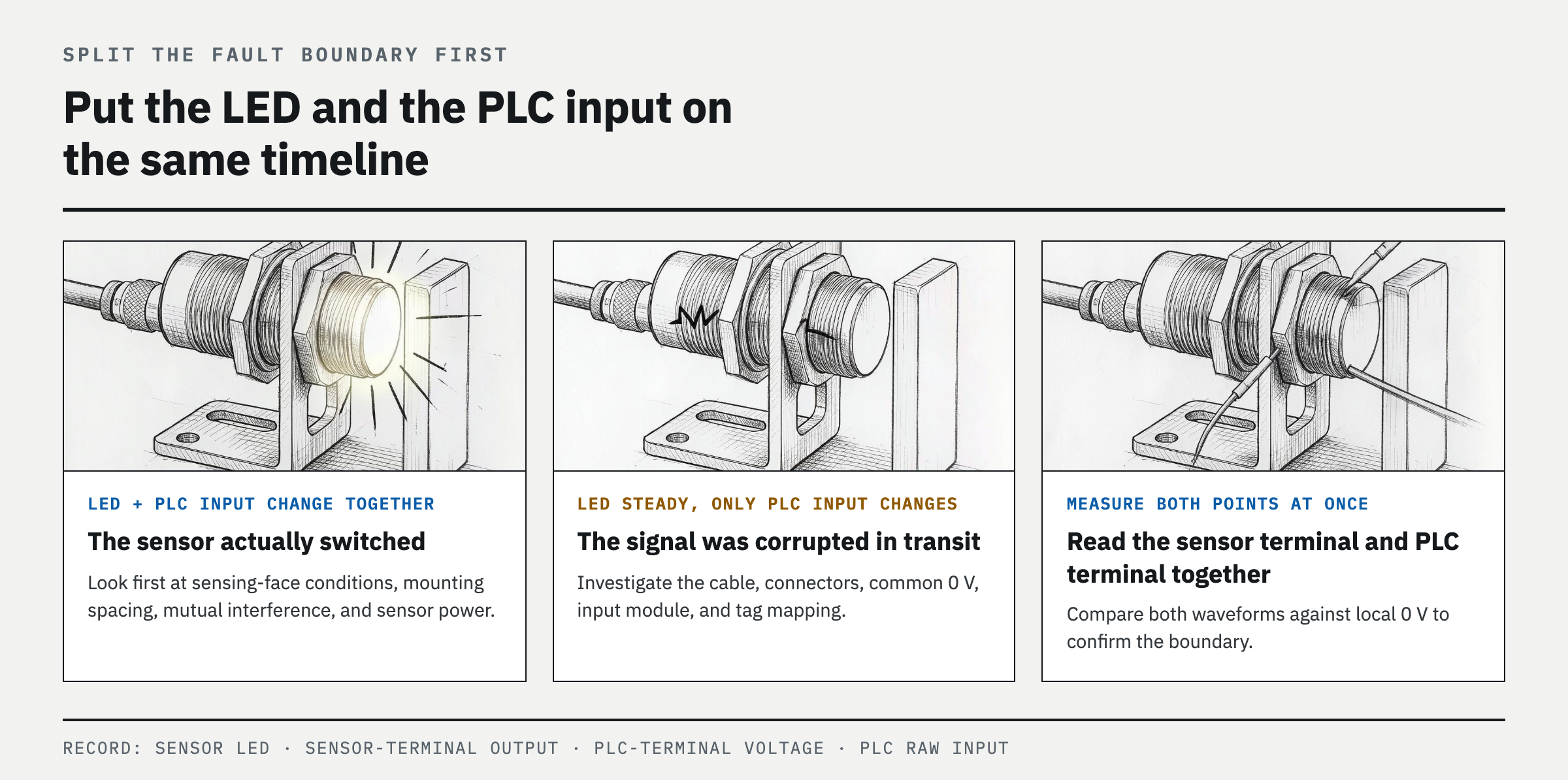
If both the sensor LED and the raw PLC input bit change during a false trigger, first investigate the actual conditions at the sensing face, mounting clearance, mutual interference, and sensor power. If the LED remains stable but only the PLC bit changes, the cable, connector, common 0 V, input module, or tag mapping is more likely at fault. If the LED changes but the output voltage does not, first check the model-specific circuit diagram to determine which point in the circuit the LED represents, then measure output-stage overload protection behavior, two-wire sensor residual voltage, and the input threshold. The LED may not visibly indicate a short pulse. Record the raw input rather than a processed tag with forces, latches, edge logic, or timers, and first verify that the PLC scan, input filter, task period, and logger minimum capture width can detect the expected pulse. Also record whether the event coincides with motor starting, solenoid de-energization, welding, washdown, temperature changes, a particular product material, or cable movement.
Likely causes — in the order most often encountered in the field
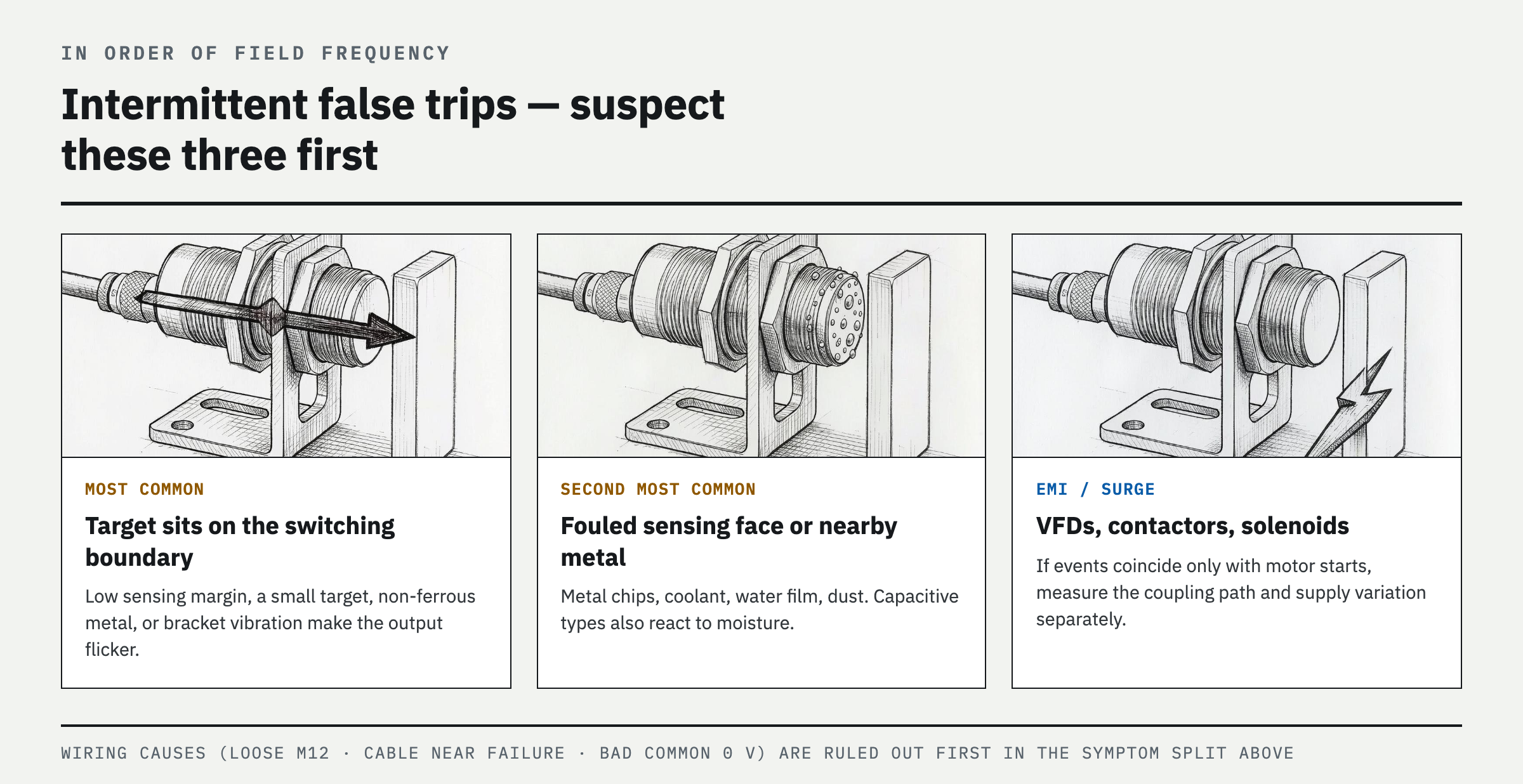
First, the target may be sitting at the switching threshold. Insufficient sensing margin, a small target, reduced range for nonferrous metals, shaft runout, a loose bracket, or repeated travel across the hysteresis boundary can make the output chatter. Second, metal chips, cutting fluid, a film of water, dust, or surrounding metal may be affecting the sensing face. Capacitive sensors in particular can respond to moisture and buildup. Third, the cause may be a loose M12 connector, a cable conductor close to breaking, a poor common 0 V, supply-voltage drop, or an incorrect PNP, NPN, or two-wire input combination. Fourth, electromagnetic interference or surges may be coming from VFD motor leads, contactors, or solenoids. Fifth, nearby sensors of the same type may be interfering with each other, or an unshielded inductive sensor may be mounted too deeply in metal. Finally, temperature, chemicals, or shock may exceed the product rating; the PLC input filter, debounce, or program edge detection may not suit the actual process; or the sensor itself may have deteriorated.
Diagnose by cause — change only one boundary at a time
First record the model's assured operating distance, standard target material and dimensions, mounting requirements, and mutual-interference spacing from its datasheet. If the output becomes stable with the target fixed at a stable position within the assured sensing range, correct the sensing margin, alignment, material, or target size. After LOTO, clean the sensing face and inspect the bracket, connector, and cable. Perform any energized reproduction test remotely only after guards have been restored and personnel have cleared the area. Measure the sensor-terminal output and PLC-terminal voltage together relative to the local 0 V, and record the potential difference between the local 0 V and PLC 0 V as well as simultaneous events from other sensors on the common distribution box. Because a multimeter may average out and miss short pulses, a qualified person must use appropriately rated isolated or differential instrumentation. If events are synchronized with motor starting, compare event counts under identical production conditions between the original cable route and an approved temporary alternate route. Disable an adjacent sensor for testing only with sensor types subject to mutual interference, such as inductive sensors. Substitute a spare or swap positions only when the model, NO/NC state, PNP/NPN or two-wire circuit, and sensitivity or teach settings match, and change either the sensor or its position—not both—at one time.
Corrective procedure — fix physical conditions first, then electrical conditions and logic
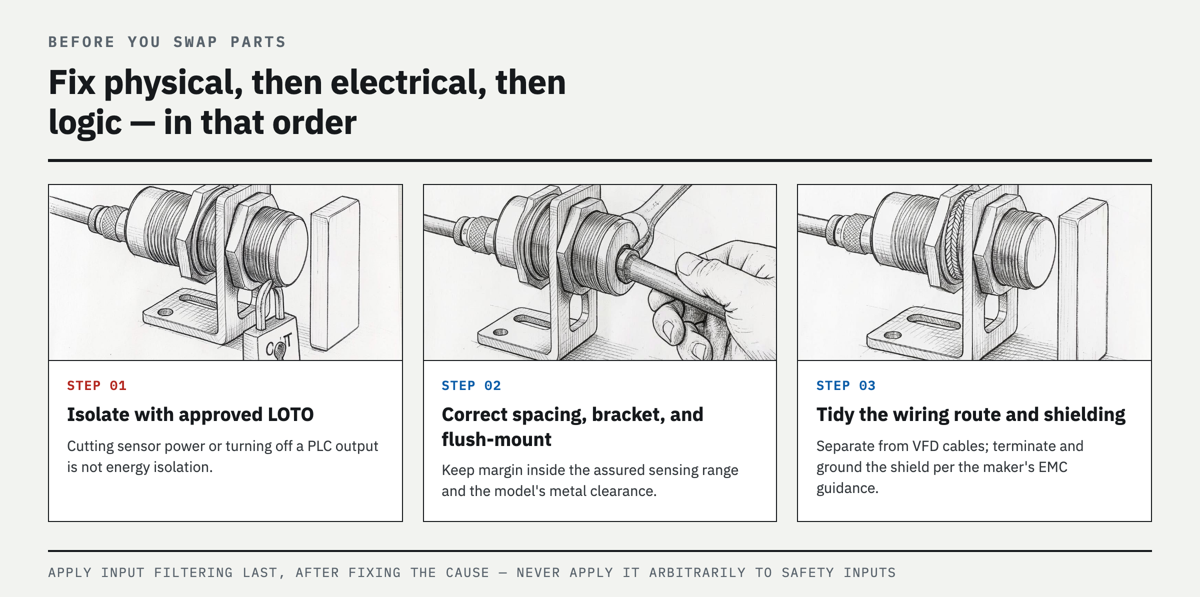
Adjust the sensor position and a rigid bracket so the target remains well within the model's assured sensing range. Maintain the model-specified metal clearance and sensor spacing for shielded and unshielded versions. Remove contamination from the sensing face using a cleaning method verified against the SDS and material compatibility. Use a compressed-air purge only when approved by the manufacturer and when debris shielding and dust collection are provided; never direct compressed air at a person or skin. Replace damaged cables and connectors with specified parts, correct bend radius, tension, and ingress paths, and measure supply voltage and 0 V while the sensor is loaded and interference sources are operating. Follow the equipment, sensor, and drive manufacturers' combined guidance for signal routing, shield termination, grounding, and coil surge suppression. Do not alter certified barrier, grounding, or wiring conditions in hazardous-location or intrinsically safe circuits. Do not use a PLC input filter as the first step to mask the cause. Apply one only after process timing, stopping distance, interlock sequence, and a risk assessment confirm that the pulse can safely be ignored. Do not add ordinary software debounce to a safety function without authorization and validation.
Prevent recurrence — make sensing margin and event records maintenance items
During equipment acceptance, confirm stable ON and OFF positions under the target material, minimum size, worst-case alignment, temperature, and contamination conditions, then retain photographs of the correct installation and the reference clearance. Add loose sensors, cable abrasion, connector ingress, chip buildup, and discoloration at power terminals to shift inspections. For maintenance purposes, have the PLC record the count of short ON and OFF pulses on the raw input and the time of the last event, but keep this logging separate from control logic. Where several similar sensors are installed, do not replace them all at once; use position-swap tests and fault history to identify a common cause. When equipment is expanded, treat adding VFD cables and sensor wiring to the same duct or installing a sensor immediately beside an existing sensor as changes requiring EMC and mutual-interference review.
FAQ
Why does my inductive proximity sensor flicker on and off?
This commonly occurs when the target is at the edge of the assured sensing range or when bracket vibration, surrounding metal, metal chips, or interference from an adjacent sensor repeatedly moves the oscillator across its switching threshold. Move the target closer to the sensor and secure it to see whether the output stabilizes, then compare the installation against the model-specific mounting requirements and minimum sensor spacing.
Can electrical noise cause a proximity sensor to false trigger?
Yes. VFD output leads, contactors, and solenoid coils can couple noise into the signal wiring or disturb the sensor supply and common 0 V. Record the sensor LED, field output voltage, and PLC input together to determine whether the noise enters before or after the sensor output, then correct the installation according to the manufacturer's EMC wiring guidance.
Why does my proximity sensor trigger when no metal is present?
For an inductive sensor, first check for metal chips on the sensing face, nearby brackets or guards, incorrect metal embedment of an unshielded sensor, and interference from an adjacent sensor. A capacitive sensor can respond to moisture, powder, an oil film, or an approaching operator even when no metal is present, so first confirm the sensing technology and sensitivity setting.
Should I add a PLC debounce timer to stop sensor false triggers?
First eliminate installation, contamination, wiring, power, and electromagnetic-interference causes. Apply the minimum filter only after verifying that any remaining short pulse is not a real target and can be ignored without affecting process operation or safety. Do not arbitrarily add a standard timer to a safety input.
References
- OMRON, Proximity Sensors Technical Guide (CSM_Proximity_TG_E_6_1)
- OMRON, E2B Proximity Sensor Instruction Sheet, Mutual Interference
- Pepperl+Fuchs, Installation Conditions for Inductive Sensors (TDOCT-6596)
- Pepperl+Fuchs, Operating Distance as Central Characteristic
- OSHA, 29 CFR 1910.147, The Control of Hazardous Energy
Spotted an error or have a question about this guide? Email contact@fixtheplant.com — corrections are prioritized.