
Sensors & PLC / PLC I/O & Wiring
Troubleshooting a 4-20mA Signal That Reads Zero
- Doc
- 4-20ma-signal-reads-zero
- Section
- sensors-plc/plc-io
- Revised
In a 4-20mA loop, 4 mA is the "live zero" that represents the bottom of the measuring range, so an actual 0 mA is not a normal process value — it signals lost power, an open circuit, or a disabled output. But a 0 on the operator screen may simply be 4 mA correctly scaled to 0% or to the low engineering value. So do not start swapping parts. Compare the displayed value, the PLC raw count, and the actual loop current in that order to narrow down where the fault lies.
Key Specifications
| Specification | Value | Source |
|---|---|---|
| Normal bottom of the measuring range | 4 mA is the usual 0% process value and 20 mA the 100% value. A 0% on the screen and a measured 0 mA therefore do not mean the same thing. | Fluke, What Is a 4-20 mA Current Loop? |
| An actual 0 mA | In a typical 4-20mA loop this is a fault indication that points first to an open circuit, a bad connection, or lost power. | NI, 4-20 mA Current Loop Fundamentals, System Design, and Setup |
| 4 mA simulated input | If the input channel and scaling are correct, the HMI or controller should display the configured bottom of the measuring range, normally 0%. | Fluke, Troubleshooting a 4-20 mA Loop Using mA Simulate |
| 20 mA simulated input | If the input channel and scaling are correct, the HMI or controller should display the configured top of the measuring range, normally 100%. | Fluke, Troubleshooting a 4-20 mA Loop Using mA Simulate |
| Failure signal current | Devices following NAMUR NE 43 report a fault not as exactly 0 mA but as a current below (commonly 3.6 mA or less) or above (commonly 21 mA or more) the measuring range. So 0 mA is more likely a circuit or power problem than an NE 43 style device self-diagnostic. Confirm the values actually applied in the manuals for that transmitter and input module. | NAMUR, NE 43 — Standardisation of the Signal Level for the Failure Information of Digital Transmitters |
Types & Variations
2-wire loop-powered transmitter
The same two wires carry both operating power and the 4-20mA signal, with the transmitter regulating the loop current.
Use: If there is no voltage at the field terminals, look at power, wiring, and the input path first. When testing, confirm how the transmitter combines with a SIMULATE function that relies on the external loop supply.
3-wire and 4-wire separately powered transmitter
Device power and the current output can have a separate common or circuit, so the output can sit at 0 mA while the display stays lit.
Use: Measure the device supply and the output loop separately, and confirm whether the output is active or passive, and what its common reference is, from the manufacturer's wiring diagram.
Passive input versus active input
A passive input needs an external loop supply, while an active input supplies loop power from the channel. Manufacturers name these differently.
Use: Use this when pairing a transmitter type to an input card type. Give priority to the actual circuit diagram and terminal descriptions to avoid both no-power and power-conflict wiring.
Maintenance Steps
- Confirm the operational impact and isolate energy
Confirm with the operations team how this signal affects interlocks, trips, valves, and automatic operation. Bring the equipment to a safe stop, identify electrical, pneumatic, hydraulic, gravitational, spring, and thermal energy, and isolate using your site's approved LOTO procedure.Putting the PLC in STOP or merely switching outputs off is not energy isolation. Breaking the signal can trigger the fail-safe action of a valve or drive, so hand the process over safely before opening the loop.
- Release residual pressure and stored energy, then verify the zero-energy state
Isolate the impulse lines and manifolds of pressure, flow, and level instruments in the approved sequence, and relieve residual pressure at the designated drain or vent points. Dissipate or restrain stored energy in accumulators, capacitors, and rotating masses, and verify the zero-energy state with an approved instrument.A gauge reading 0 does not rule out pressure trapped behind a plugged impulse line or a check valve. Never loosen a fitting or transmitter to bleed residual pressure, and route toxic, flammable, or hot fluids to the designated collection system.
- De-energized visual and continuity checks
Working against the drawings and terminal numbers, check fuses, disconnect terminals, polarity, looseness, corrosion, moisture, and cable damage. Suitably disconnect sensitive electronics from the circuit, then confirm continuity section by section per approved procedure.Never bypass barrier grounding or wiring in an intrinsically safe circuit, and never connect a megger to one. Instruments and test methods must suit the explosion-protection and intrinsic-safety design and the conditions of the work permit.
- Controlled live voltage and current measurement
Restore guards and enclosures, clear people from the hazard zone, then re-energize under an approved test procedure. Compare voltages at the power supply, the input card, and the field terminals, and confirm the actual loop current with an mA clamp or a suitably rated meter connected in series.A series current measurement breaks the loop and disturbs the process. Connecting a meter in current mode across a supply can cause a short circuit and blow the meter fuse, so re-check the rating, lead sockets, polarity, and connection method.
- Isolated simulated-input testing and functional verification
Disconnect the transmitter, mark its polarity, and apply 4 mA and 20 mA to the input path using the correct SOURCE or SIMULATE mode on the calibrator. Check the PLC raw value, status bits, engineering value, and HMI, then test the transmitter separately and compare both sets of results.Apply approved override and bypass procedures so that test currents cannot defeat a safety instrumented function or move a real output, and after testing remove every force and bypass with independent confirmation.
Confirm the symptom — separate a displayed 0 from a real 0 mA
If the HMI shows 0 but roughly 4 mA is flowing at the PLC input terminals, the current path itself is intact, so the process is probably genuinely at the low end or the scaling and tag mapping are wrong. However, seeing 4 mA is not proof that the transmitter is responding to the process. A held output, simulation mode, or a sensor fault that pins the output at the low limit all produce the same 4 mA, so stimulate the process or check the transmitter status as well. Conversely, if a calibrated meter reads an actual 0 mA and the input channel's OpenWire or Underrange diagnostic is also set, trace lost power or an open circuit first. Record whether the transmitter display is dark, what the PLC raw count and channel status bits are, and whether the local indication matches the real process. A multimeter with a blown current fuse makes a healthy loop look like 0 mA in a series measurement, so check the meter fuse and lead sockets before measuring. Note also that 3-wire and 4-wire transmitters keep their separate supply, so the display can stay lit while only the output circuit is broken.
Likely causes — ordered from the least invasive check
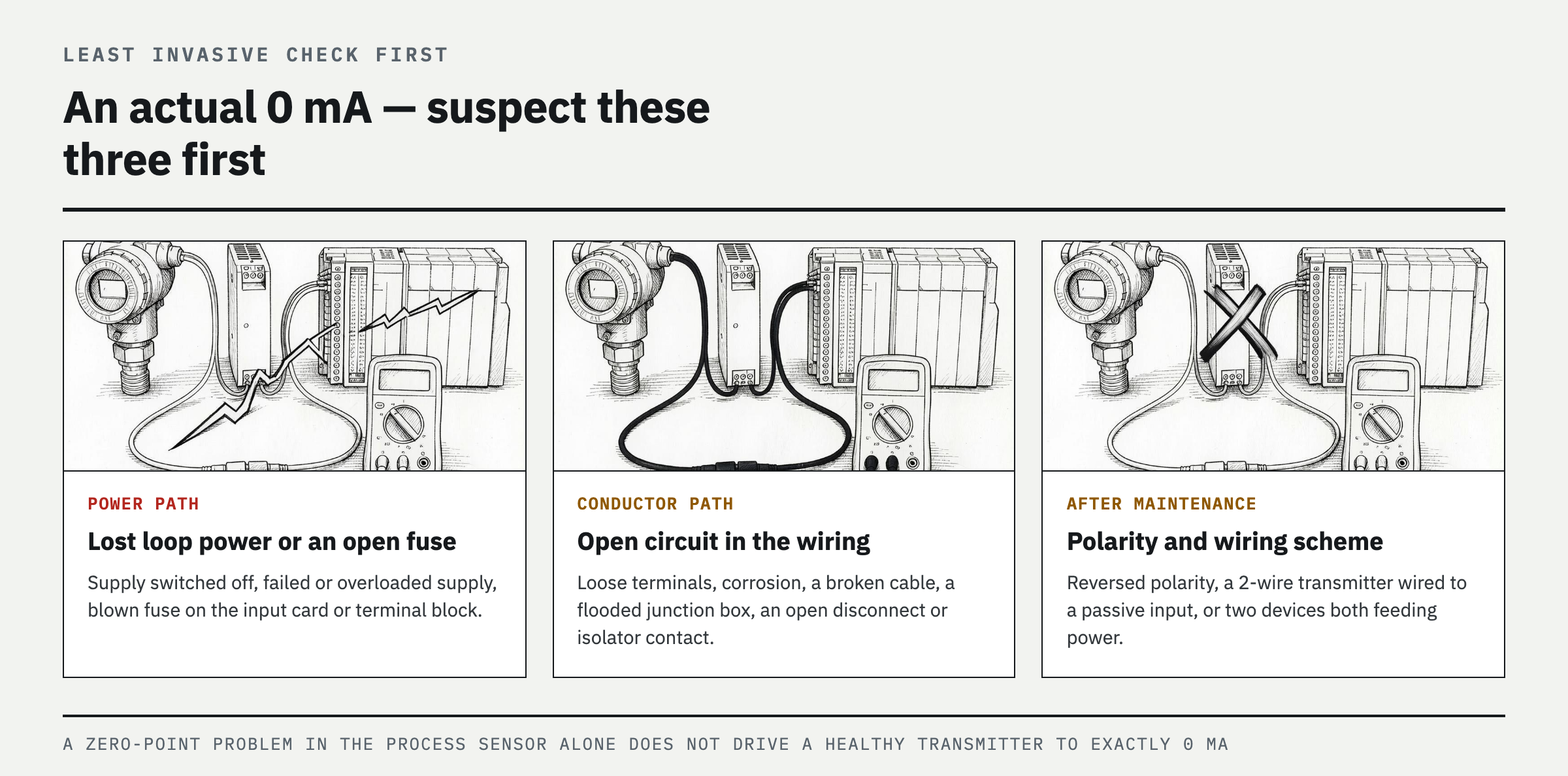
First: loop power switched off, a failed or overloaded power supply, or a blown fuse on the input card or terminal block. Second: loose terminals, corrosion, a broken cable, a flooded junction box, or an open contact in a disconnect terminal or isolator. Third: reversed polarity after maintenance, a 2-wire transmitter wired as if to a passive input, or two devices both supplying power and fighting each other. Fourth: configuration errors — the PLC channel set to voltage, 0-20mA, or disabled, or the wrong channel or HMI tag being read. Fifth: an inadequate loop voltage budget, where total load resistance and cable voltage drop leave the transmitter without its minimum operating voltage. Last: an actual failure of the transmitter output stage, the barrier or isolator, or the analog input card itself. A zero-point problem in the process sensor alone does not normally drive a healthy 4-20mA transmitter to exactly 0 mA.
Diagnosis by cause — cut the fault boundary with voltage points and simulated current

Using approved procedures and suitable instruments, compare voltage in turn at the power supply output, the input card side, and the field transmitter terminals. If voltage is present at the supply but not in the field, trace the fuses, terminals, cable, and barrier between them section by section. If the field terminals have enough operating voltage for that model but current is still 0 mA, suspect polarity, transmitter wiring, or an output failure. Judge the exact permissible voltage and maximum load from that model's datasheet — do not assume "24 V is fine for every loop." Disconnect the transmitter and apply 4 mA and 20 mA to the input side using mA SIMULATE mode, which draws on the external loop supply. If the PLC then reads the configured low and high limits, the input card, wiring, and scaling are broadly healthy and the search narrows to the field transmitter. If instead the PLC still reads zero with simulated current injected directly at the input card terminals, check channel configuration, terminals, the input fuse, and the card diagnostics. Confusing SOURCE with SIMULATE, or connecting an ammeter in parallel, invalidates the test and can blow fuses.
Decision table by measurement result — pinpoint the guilty section
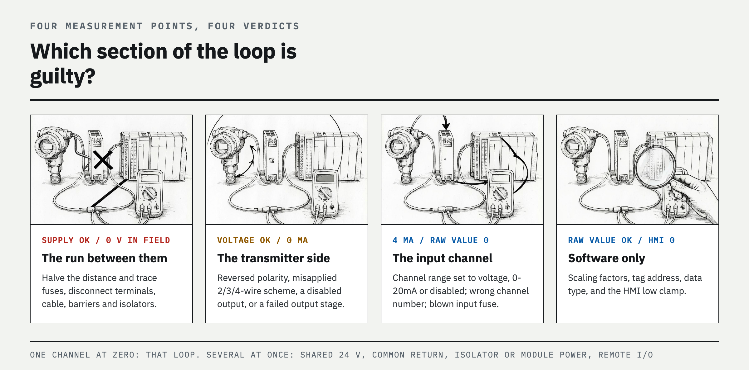
Four measurement points (power supply output, field transmitter terminals, actual current at the input card terminals, and PLC raw value) sort the fault into sections. (1) Supply output normal but 0 V at the field terminals: the culprit is the run between them — halve the distance and trace fuses, disconnect terminals, cable, and barriers or isolators. (2) Field terminals have the operating voltage the datasheet requires but current is 0 mA: the culprit is on the transmitter side — check reversed polarity, a misapplied wiring scheme (2-, 3-, or 4-wire), a disabled output, or a failed output stage. (3) Loop current is 4 mA but the PLC raw value is 0: the culprit is the input channel — check the channel range setting (voltage / 0-20mA / disabled), the channel number, and the input fuse. (4) Raw value is correct but only the HMI shows 0: the culprit is software — check the scaling factors, tag address, data type, and low clamp. Now overlay one more axis, the number of affected channels: if only one channel is zero, look at elements specific to that loop; if several channels go to zero at once, suspect the shared 24 V supply, the common return, isolator power, module power, or remote I/O communications first. Always check this branch before replacing several individual transmitters at once.
Repair procedure — restore the open circuit, then verify the full range
With LOTO applied and residual pressure released, replace a blown fuse with the specified rating only after removing the short or overload that caused it, and restore damaged, corroded, or water-ingressed terminals and cable to approved specification. Re-establish polarity, the 2-wire, 3-wire, or 4-wire scheme, and the active/passive input pairing against the actual terminal numbers in each device manual. If the total load exceeds the permitted value, remove unnecessary series devices or redesign with a supply and isolator arrangement the manufacturer allows. Set the channel to the 4-20mA range with the correct tag, and build the OpenWire and Underrange diagnostics into the control strategy. After the repair, test 4 mA and 20 mA with a calibrator, adding a midpoint if needed, and confirm that the PLC raw value, engineering value, and HMI display all agree. Finally, apply real process input and confirm the transmitter holds 4 mA even at the bottom of its range.
Prevent recurrence — keep baseline voltages and diagnostic bits as maintenance assets
During normal operation, record the voltages at the power supply, the input card, and the field transmitter terminals, along with the loop current, so the next fault has a baseline to compare against. Mark every fuse, surge protector, barrier, isolator, and disconnect terminal on the terminal drawings, and document the actual configuration of spare channels too. In the PLC, do not monitor only the engineering value — log the per-channel OpenWire, Underrange, and communication or module fault bits together with the alarm cause. Include junction box moisture, arbitrary shield grounding or shield breaks that contradict the drawings and the grounding design, loose terminals, cable glands, and power headroom in routine inspections. Do not hide a 0 display behind an input filter or an HMI low clamp, and keep the low-current diagnostic and the process low-low alarm as distinct messages so operators never confuse the bottom of the process range with an instrument fault.
FAQ
My 4-20mA signal reads 0 mA — what should I check first?
Work through loss of loop power, an open fuse, a broken wire or loose terminal, and reversed polarity, in that order. Check the field terminal voltage and the input card diagnostic bits first, then use a calibrator to test the input path and the transmitter separately and cut the fault boundary. A normal process low end is 4 mA, not 0 mA.
Can 0 mA ever be normal?
During normal operation, essentially never. It may not be a fault if the device has not yet started up or is shut down, if the output is disabled or de-forced, or if a 3-wire or 4-wire active output is switched off. Devices following NAMUR NE 43 report their own faults as currents outside the measuring range rather than as 0 mA, so 0 mA usually points to a circuit problem, not a device diagnostic.
The transmitter has voltage, so why is the current 0 mA?
Voltage alone does not prove the current path is complete. Look at reversed polarity, a power conflict from connecting an active input to a 2-wire circuit, a misapplied wiring scheme, or a failed output stage. In 3-wire and 4-wire devices the supply and output circuit are separate, so the display can be lit while only the output is broken.
The loop measures 4 mA but the PLC shows 0. Is that a fault?
It may be a correct display of 4 mA scaled to an engineering value of 0 or to 0%. If the process is not actually at the low end, cross-check the channel range, raw value scaling, tag address, HMI low clamp, and transmitter range settings. Also confirm that a 20 mA simulated input displays as the configured upper limit.
Several analog inputs read zero at the same time — now what?
Check the shared elements before pulling individual transmitters apart. A common 24 V supply, a common return, isolator power, module power, or a loss of remote I/O communications can drive several channels to zero at once. Starting with individual component replacement on a multi-channel failure only burns time and spares.
How do I measure a 4-20mA loop with a multimeter?
Current is measured with the meter in series with the loop, so the circuit is briefly broken and control outputs can move. Get operational approval and check the rating, fuse, and lead sockets before connecting. Where possible use a process mA clamp that does not break the circuit, but confirm from the specification that it is a model that reads 4-20mA DC at the resolution you need. Never connect a meter in current mode across a supply.
References
- Fluke, What Is a 4-20 mA Current Loop?
- Fluke, Troubleshooting a 4-20 mA Loop Using mA Simulate
- Fluke, How to Measure a 4-20mA Loop Signal
- NI, 4-20 mA Current Loop Fundamentals, System Design, and Setup
- NAMUR, NE 43 — Standardisation of the Signal Level for the Failure Information of Digital Transmitters
- OSHA, 29 CFR 1910.147, The Control of Hazardous Energy
Spotted an error or have a question about this guide? Email contact@fixtheplant.com — corrections are prioritized.