
Sensors & PLC / Encoders & Position Feedback
Why Is My Encoder Losing Counts Intermittently?
- Doc
- encoder-losing-counts-intermittently
- Section
- sensors-plc/encoders
- Revised
This article covers intermittent discrepancies between the actual travel of an incremental rotary encoder and the count reported by a PLC or drive. Although these failures appear to have many possible causes, monitoring just three points at once—the shaft witness mark and the waveforms at both ends of the signal path—quickly reveals whether pulses are being lost in the mechanical transmission, signal transmission, or counter processing. Replacing the encoder or increasing the input filter before identifying that boundary only masks the cause temporarily.
Key Specifications
| Specification | Value | Source |
|---|---|---|
| Counts are correct at low speed but fall short only at high speed | Compare the required pulse frequency with the encoder's maximum response frequency, the receiver's maximum input/counting frequency, and the input filter. Calculate rotational speed (r/min) ÷ 60 × pulses per revolution, and allow margin in the selected model's rating for actual period variation. | OMRON, Technical Explanation for Rotary Encoders — maximum response frequency and selection margin |
| The waveform is normal at the encoder terminals but its edges are distorted at the receiver terminals | Investigate cable length and capacitance, connectors, output/input compatibility, twisted pairs, shielding, and differential termination. Long cables increase rise time and may affect A/B phase characteristics and response frequency. | OMRON, FAQ01004 for Rotary Encoders — cable extension lengthens signal rise time and shifts read timing; Encoder Products Company, WP-2004 Encoder Noise Reduction Strategies — cable capacitance and termination |
| Errors occur at the same time as VFD, brake, or relay operation | Check power and signal cable routing, ground loops, encoder power, and shield termination, and measure A/A̅ and B/B̅ differentially. Compare the same operating condition using an approved temporary routing path to narrow down the coupling path. | OMRON, Correct use of Rotary Encoders — wire the encoder separated from power lines or in separate shielded conduit; OMRON, FAQ00969 for Rotary Encoders — twisted-pair cable for RS-422A noise cancellation |
| The shaft returns to its reference position, but the hub witness marks do not realign | Repair slip or misalignment in the coupling, belt, hollow-shaft clamp, torque arm, or measuring wheel first. Do not compensate for mechanical slip with counter or PLC correction values. | British Encoder Products Company, Trouble Shooting Guide for Incremental Encoders — anti-rotation mounting, coupling tightness and slip, belt tension |
| The error increases in one direction or during direction reversals | Verify the presence and wiring of both A/B channels, phase sequence, and receiver counting mode. At the same time, check backlash and coupling windup. Compare raw counter values rather than processed display values. | British Encoder Products Company, Trouble Shooting Guide for Incremental Encoders — wiring and signal-compatibility checks; OMRON, Technical Explanation for Rotary Encoders — phase-difference output |
Types & Variations
Single-ended open-collector or push-pull output
Wiring is simple, but the signal depends on the common reference and receiver threshold, and its margin may decrease with cable length, frequency, and electrical noise.
Use: Use for short, low-noise runs, and verify the supply voltage, output type, pull-up, and receiver-input compatibility in the model manuals.
Differential line-driver output
A differential receiver uses the complementary A/A̅ and B/B̅ signals to reject common-mode noise. A differential output provides no benefit if the receiver or termination is incompatible.
Use: For long cables, high pulse frequencies, or electrically noisy equipment, use a compatible line receiver together with the specified twisted pairs and termination.
Hollow-shaft or measuring-wheel mounting
This arrangement reduces the need for a separate coupling, but a loose clamp or torque arm, or insufficient wheel contact force, can miss actual travel even when the electrical signal is normal.
Use: Use for conveyor length measurement or direct motor-shaft mounting, and add witness marks to distinguish slip from electrical count loss.
Maintenance Steps
- Stop the equipment and isolate all energy sources
Stop rotating components and conveyed material in a safe position, and support gravity loads with rated blocking or supports. Follow site procedures to lock out and tag out electrical, pneumatic, hydraulic, mechanical, and thermal energy, and secure the shaft against rotation from inertia or external force.A stop button, emergency stop, PLC output OFF state, or disconnected encoder power is not energy isolation. Physically prevent unexpected startup and shaft rotation before reaching inside a guard.
- Release residual pressure and stored energy, then verify a zero-energy state
Use the designated discharge paths to release residual pressure from pneumatic and hydraulic lines and accumulators. Release or restrain spring, gravity, shaft-inertia, and capacitor energy. Using approved instruments and site procedures, verify zero voltage, zero pressure, and the inability to restart.A pressure gauge may read zero while pressure remains trapped behind a check valve or inside a cylinder chamber. Do not loosen fittings to bleed residual pressure, and follow the drive manufacturer's specified capacitor discharge wait time.
- Inspect the mechanical transmission and de-energized wiring
Apply aligned witness marks across the shaft, hub, and coupling, then inspect fastening, alignment, bearing play, the torque arm, and measuring-wheel contact. Compare the connectors and cables against the drawings for abrasion, crushing, water ingress, flex-point damage, loose terminals, output type, and pinout.Secure the load against back-driving before turning any rotating component by hand. Do not overtighten a coupling or hollow-shaft clamp to an arbitrary torque without the manufacturer's limits.
- Locate the fault boundary with a controlled energized test
With power off, install probes at approved test points and guard exposed conductors. Restore guards and protective devices, clear personnel from the area, and energize the equipment under the approved procedure. Record the encoder-terminal waveform, receiver-terminal waveform, raw counter, and timing of interference sources together. After the test, isolate the equipment again and apply LOTO before making corrections.Energized waveform measurements must be performed by qualified personnel using insulated or differential test equipment rated for the circuit and environment. Connecting the ground clip of a standard earth-referenced oscilloscope to an arbitrary signal conductor can cause a short circuit, electric shock, or equipment damage.
- Verify the repair across the full operating range
Correct only one cause at a time, then run the same reference travel at low speed, maximum required speed, in both directions, and through repeated direction reversals. Confirm that the mechanical witness marks remain aligned, the raw counts match consistently, and the A/B waveforms do not lose valid edges. Save the results as baseline data.Even if an input filter or software correction eliminates the error, do not approve safety-related position or speed functions for operation without separate validation. Use a certified safety encoder and the applicable validation procedure for safety functions.
Monitor three points at once to isolate the faulty section
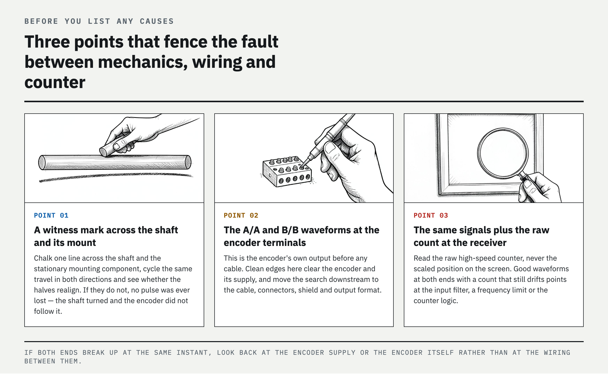
Before listing possible causes of encoder count loss, isolate the faulty section. Check three points. First, place a witness mark across the shaft and stationary mounting component, cycle the same travel in both directions, and verify that the marks realign. Second, measure the A/A̅ and B/B̅ waveforms at the encoder terminals. Third, measure the same signals at the receiver terminals—the PLC high-speed input module or drive—and record the raw counter value at that instant. The combination of these three observations determines the fault location. If the witness marks do not realign, there is no need to troubleshoot the electrical circuit: the coupling, hollow-shaft clamp, torque arm, or measuring wheel is slipping. If the marks realign and the waveform is clean at the encoder but its edges collapse at the receiver, the fault lies in the cable, connector, shield, or an output/input format mismatch. If the waveforms are normal at both ends but the raw count is wrong, investigate the input filter, response-frequency limit, and counter logic. If both waveforms become unstable at the same instant, investigate the encoder power supply or the encoder itself. Always record the raw high-speed counter value rather than the displayed position so scaling, reset, and latch errors do not contaminate the diagnosis.
Five loss patterns and what each one indicates
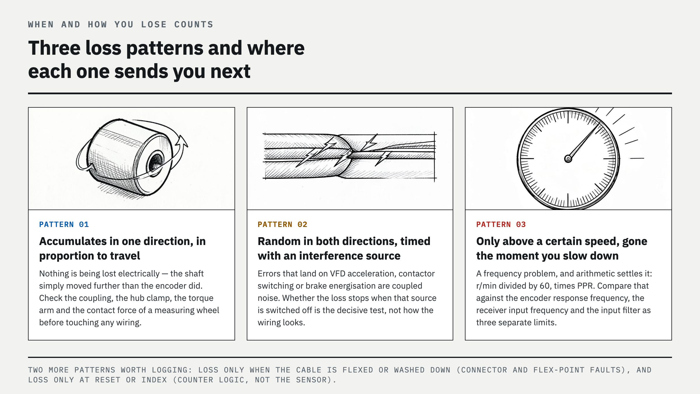
When and how counts are lost already narrows the cause. ① The error accumulates in only one direction and in proportion to travel: mechanical slip. The electrical signal is not being lost; the shaft has actually turned farther than the encoder, so inspect the coupling, hub clamp, and measuring-wheel contact force. ② The error occurs randomly in either direction and coincides with VFD acceleration, contactor switching, or brake energization: coupled electrical noise. The decisive test is whether the problem disappears when the interference source is disabled. ③ The error occurs only above a specific speed and disappears immediately below it: a frequency problem, confirmed by the pulse-frequency calculation below. ④ The error occurs only when the cable moves or during washdown or temperature rise: a connector contact problem, an internal conductor break at a flex point, or a loose common conductor. ⑤ The error occurs only during a reset or index-channel (Z-phase) transition: a race condition involving the counter preset, latch, overflow, or task cycle rather than the sensor. If the symptom fits none of these five patterns, more data is needed. Record the number of direction reversals, maximum speed, drive operating state, and exact time of each discrepancy, then reproduce the fault again.
Settle it with numbers—required pulse frequency versus rated response
Pattern ③ is resolved by calculation, not guesswork. Required frequency = rotational speed (r/min) ÷ 60 × pulses per revolution (PPR). At 1800 r/min and 1024 PPR, 30 rev/s × 1024 = 30.7 kHz. If the receiver uses x4 quadrature decoding, the count rate is approximately 123 kcps. Compare these two values separately with three different specifications: the encoder's maximum response frequency, the receiver input's maximum input frequency—checking whether the manual defines it before or after quadrature multiplication—and the input filter time constant. If the calculated value approaches any one of these limits, that point is the likely cause. Cable length further reduces the available margin. A long cable's capacitance increases rise time, so the waveform may still be visible while valid edges fail to cross the receiver threshold. This is why a system with adequate catalog margin can still undercount only at high speed on the installed wiring. Before reducing or disabling the filter, use the waveform to determine whether it was rejecting noise or valid pulses.
Distinguish a real repair from a workaround that only masks the fault
After applying LOTO and releasing stored energy, work on only the section identified above. Restore a slipping hub, coupling, or torque arm to the manufacturer's installation dimensions and fastening requirements, and replace damaged components. Separate encoder cables from power wiring, eliminate unnecessary intermediate splices and water-ingress paths, and use the specified twisted pair, shielding, grounding, and termination. If the output and input formats are incompatible, do not add an improvised resistor; install a compatible line-driver and line-receiver combination. By contrast, three measures only mask the cause: indiscriminately increasing the input filter, periodically correcting the counter in the PLC, and swapping encoders until the symptom disappears. A larger filter suppresses both noise and valid pulses, so do not apply it to signals used for safety, stopping distance, or positioning without repairing the cause and completing a risk assessment. After the repair, run the same reference travel at low speed, maximum required speed, and repeated reversals in both directions. Verify that the witness marks realign and the raw counts match, then retain the waveforms and measured values as baseline data.
FAQ
Why is my incremental encoder missing pulses at high speed?
Calculate the required frequency as rotational speed (r/min) ÷ 60 × PPR, then check the encoder and receiver ratings separately. If counts are correct at low speed but fall short only at high speed, first investigate the input filter, cable-induced slow edges, and output/input format mismatch. Comparing the waveforms at the encoder and PLC terminals at the same time identifies where the loss occurs.
Can electrical noise make an encoder lose counts?
Yes. Noise from VFD output wiring, motors, brakes, and relays can create false edges or distort real edges below the receiver threshold. Correlate the error time with interference-source operation, separate power and signal wiring, use the manufacturer's specified shielding and grounding, and install compatible differential transmitters, receivers, and termination.
Why does my encoder count change when the cable moves?
The likely causes are a poor connector contact, a broken conductor inside a cable flex point, or a faulty common conductor. Do not move the cable by hand while the equipment is running. Apply LOTO, release residual pressure, and inspect continuity and condition section by section. If energized reproduction is required, use an approved test fixture that moves the cable remotely.
Should I replace the encoder if it intermittently loses position?
First compare the shaft and hub witness marks, the waveform at the encoder output, and the waveform at the receiver input. Misaligned mechanical witness marks indicate a mounting problem. A normal encoder output with missing pulses only at the receiver indicates a cable or interface problem. Substitute the encoder only when both measurement points are faulty at the same time and the power supply, load, and environment are normal.
References
- OMRON, Technical Explanation for Rotary Encoders
- OMRON, Correct use of Rotary Encoders
- OMRON, Safety Precautions of Rotary Encoders
- OMRON, FAQ00969 for Rotary Encoders — twisted-pair cable for RS-422A transmission
- OMRON, FAQ01004 for Rotary Encoders — causes of output data misreading
- British Encoder Products Company, Trouble Shooting Guide for Incremental Encoders
- Encoder Products Company, WP-2004 Encoder Noise Reduction Strategies for Encoders in Motion Control Applications
- OSHA, 29 CFR 1910.147 — The Control of Hazardous Energy
Spotted an error or have a question about this guide? Email contact@fixtheplant.com — corrections are prioritized.