
Power Transmission / Shaft Couplings
Why Does My Jaw Coupling Spider Keep Failing?
- Doc
- jaw-coupling-spider-keeps-failing
- Section
- power-transmission/couplings
- Revised
A spider is not simply a weak, fuse-like part that is expected to break. In a properly selected and aligned jaw coupling, eliminating the cause comes before repeatedly replacing the spider. Before cleaning or discarding the failed part, mark the driving and driven sides and the direction of rotation, then take photos. This makes it possible to trace which loads were concentrated on which faces. The sequence below starts with the most common and least costly checks in the field.
Key Specifications
| Specification | Value | Source |
|---|---|---|
| Selection Torque | Determine design torque by multiplying nominal torque by the service factor for the application, then compare it with the allowable torque and maximum speed for the selected coupling size and spider. | Lovejoy Jaw Type Coupling Catalog, Selection Process: https://www.timken.com/wp-content/uploads/2019/02/LOVEJOY_Jaw2010catalog.pdf |
| Alignment Limits | Limits vary with coupling size and speed. Do not use a generic value; apply the displacement table for the specific manufacturer and model. Exceeding the limits can damage the coupling. | KTR ROTEX Type SH Operating/Assembly Instructions, alignment and wear limits: https://www.ktr.com/fileadmin/ktr/media/Manuals/40229en000000.pdf |
| Wear Discard Limit | The backlash limit X varies by model size. For example, KTR ROTEX SH lists 3–14 mm (0.12–0.55 in) for sizes 19–180; do not apply these values to another manufacturer or model. | KTR ROTEX Type SH Operating/Assembly Instructions, Table 10: https://www.ktr.com/fileadmin/ktr/media/Manuals/40229en000000.pdf |
| Example Inspection Criterion | Lovejoy's general safety guidance states that the coupling must not be operated if the elastomer is damaged or is less than 75% of its original thickness. The product-specific manual takes precedence. | Lovejoy coupling catalog safety warning: https://www.timken.com/wp-content/uploads/2019/02/LOVEJOY_S-Flex-Catalog-Rev-A-v3-1.pdf |
Types & Variations
Compression-Type Solid-Center/Open-Center Spider
Elastomer legs are compressed between the jaws of the two hubs to transmit torque. The design is simple and easy to inspect visually.
Use: Used in common motor, pump, and fan drives. Match the shaft-end spacing, hub alignment, material, and hardness to the table for the specific coupling.
Snap-Wrap or Radially Split Spider
Can be replaced radially without moving the hubs axially; some designs are retained by a ring or collar.
Use: Useful when equipment is difficult to move and maintenance time must be minimized. Check the manufacturer's data for speed limits and assembly orientation for the applicable retaining-ring design.
In-Shear Elastomer
Uses the elastomer in shear; some designs are non-fail-safe and stop transmitting torque if the elastomer fails.
Use: Consider when metal jaw contact must be prevented or radial replacement is important. It is not a direct substitute for a conventional compression-type spider.
Maintenance Steps
- 1. Isolate Energy and Preserve Failure Evidence
Identify and lock out all electrical, hydraulic, pneumatic, spring, and raised-load energy sources. Release stored pressure and verify that rotating components have stopped completely and cannot restart. Before opening the guard, mark the hub positions and photograph the failed part's orientation and the location of all fragments.Do not stop after turning off the disconnect switch. Isolate stored pressure, backflow, suspended loads, and windmilling fans as separate energy sources.
- 2. Inspect the Hubs, Shafts, and Foundation
Remove the spider and inspect the hub jaws for cracks, burrs, and metal-to-metal contact. Check for a loose key or setscrew, shaft runout, bearing play, loose foundation bolts, and soft foot. Do not simply dress damaged jaws with a file and return them to service; determine replacement according to the manufacturer's criteria.If the shaft must be turned by hand, first verify that all energy is isolated and no one is in a pinch-point zone.
- 3. Correct Spacing, Alignment, and Selection
Set the hub spacing specified in the model's manual, then correct angular and parallel alignment with a dial indicator or laser system. Account for thermal growth and pipe strain at operating temperature. Reselect the coupling size, spider material, and hardness using actual power, speed, starting frequency, shock loading, ambient temperature, and contacting fluids. - 4. Restart and Verify
Reinstall the guard and verify that all personnel and tools are clear before removing LOTO under the approved procedure. Progress from a no-load jog to low load and then normal load, recording knocking, vibration, temperature, and current. After thermal equilibrium, recheck alignment and inspect for early uneven wear.Never open the guard or insert hands or measuring instruments while the coupling is rotating. If abnormal noise or a rapid rise in temperature or vibration occurs, stop immediately and isolate the equipment again.
Confirm the Symptoms: Preserve the Failed Part as Evidence
If you notice rhythmic knocking during operation, black elastomer dust, increased rotational backlash, or localized heating at the coupling guard, schedule a shutdown immediately. A standard compression-type jaw coupling may continue to rotate after the spider is gone because the jaws strike each other, but this is not an acceptable operating condition. Lovejoy also states that metal-to-metal contact causes loud noise and accelerated wear. Before disassembly, mark an axial reference line across both hubs and identify the driving and driven sides. Photograph the front, back, inner, and outer faces of every leg. Record whether fragments collected on only one side and whether all legs failed at the same height.
Possible Causes: In Order of Likelihood
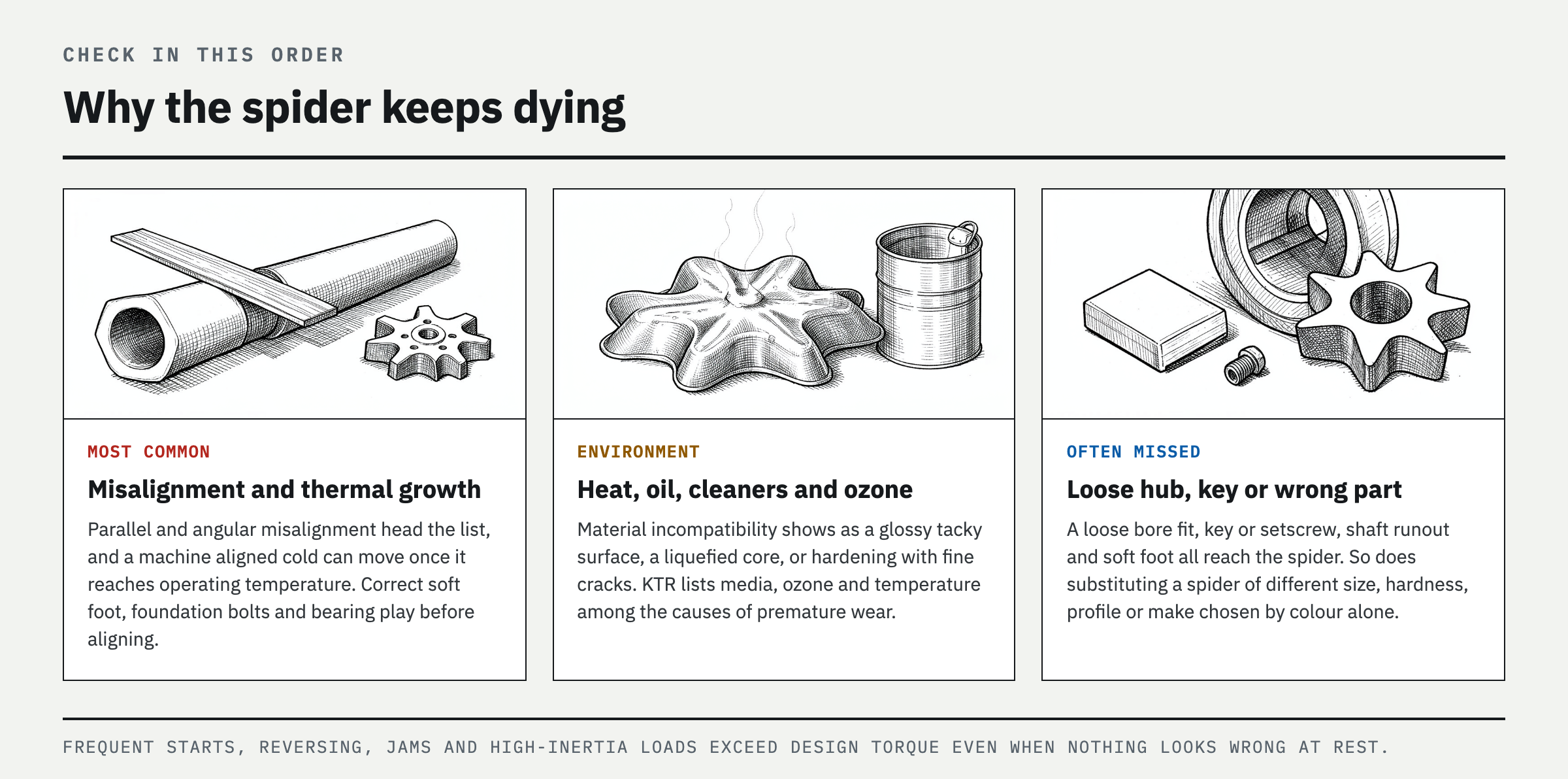
The most likely causes are parallel or angular misalignment and thermal growth at operating temperature. Second are incorrect axial spacing between the hubs or an incorrect spider installation dimension. Third is design torque being exceeded because of frequent starts, reversing, jams, or high-inertia loads. Fourth is incompatibility between the spider material and ambient heat, oil, cleaners, ozone, or other exposure. Fifth are a loose hub bore fit, key, or setscrew; shaft runout; bearing play; or soft foot. Finally, check for a selection error caused by substituting a spider of a different size, hardness, profile, or manufacturer based only on color or appearance. KTR's troubleshooting table also lists misalignment, changes in material properties caused by media, ozone, or temperature, and drive vibration as causes of premature wear.
Diagnosis by Cause: How to Read the Wear Pattern
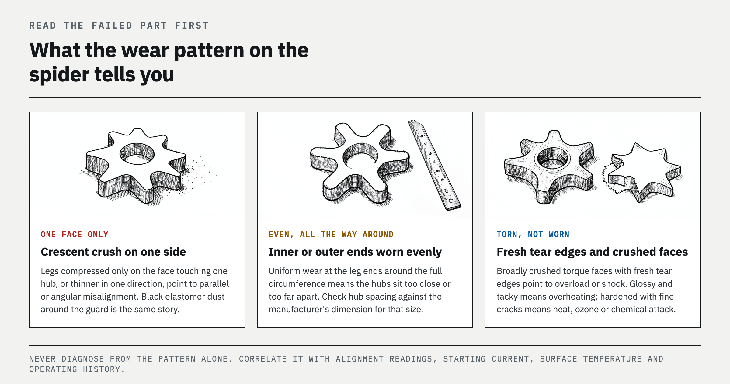
If only the face contacting one hub is compressed into a crescent shape, or if legs are thinner in only one direction, check parallel and angular misalignment first. If the inner or outer ends of the legs are worn evenly around the full circumference, the hubs are likely too close together or too far apart, leaving the axial dimension out of specification. If all torque-transmitting faces are broadly crushed and the tear edges look fresh, suspect overload or shock loading. A glossy, tacky surface or liquefied core points to overheating or vibration, while hardening with widespread fine cracks points to heat, ozone, or incompatible chemical exposure. If impact marks appear on only one hub jaw, check shaft runout, a loose hub, and key clearance. Do not make a final diagnosis from the wear pattern alone; correlate it with dial-indicator or laser alignment readings, stopping and starting current trends, coupling surface temperature, and operating history.
Corrective Procedure: Eliminate the Cause Before Replacing the Part
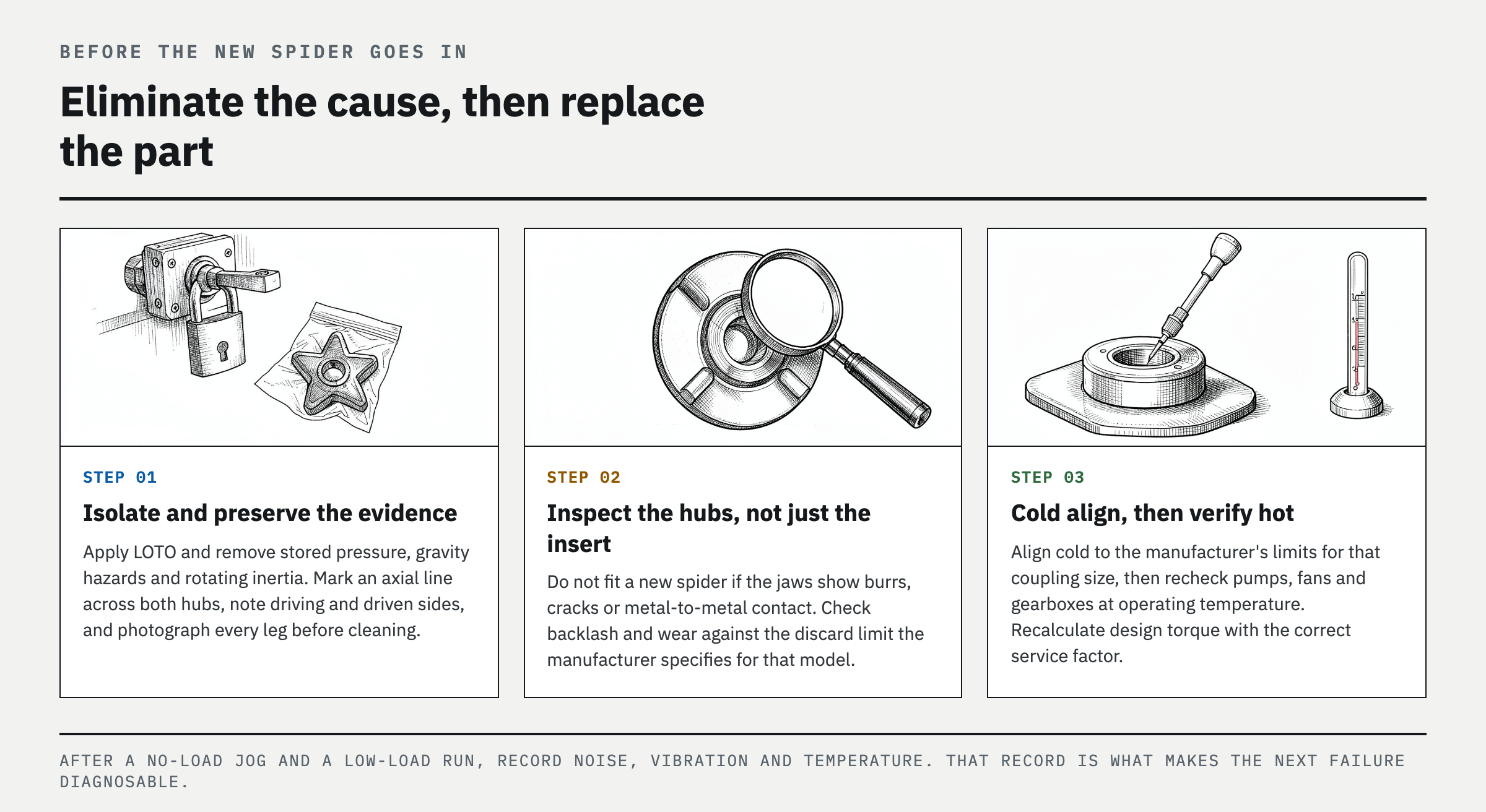
Apply LOTO and eliminate stored pressure, gravity hazards, and rotating inertia before collecting the failed part. Do not replace only the spider if the hub jaws show burrs, cracks, or metal-to-metal contact. Correct foundation bolts, soft foot, bearing play, and shaft-to-hub fastening before performing cold alignment. Use the coupling manufacturer's instructions for the target alignment limits and hub spacing for the specific coupling size, and recheck pumps, fans, and gearboxes with significant thermal growth at normal operating temperature. Then calculate nominal torque from actual motor power and speed, apply the appropriate service factor for the load, and verify the allowable torque and maximum speed of the hubs and spider. Select a material compatible with both ambient temperature and any contacting fluids. After a no-load jog and low-load run, check noise, vibration, and temperature.
Prevent Recurrence: Establish Condition-Based Limits, Not Just a Replacement Interval
Do not record only the replacement date. Keep the failed-part photos, operating hours, number of starts, alignment readings, hub spacing, surface temperature, and load events on one record. Compare alignment, temperature, and vibration immediately after the first restart and again after thermal equilibrium is reached, then open the guard after the initial operating period to check for new uneven wear. Set subsequent inspection intervals according to the manufacturer's instructions and equipment criticality, but use the discard criteria specified for the model, such as increased backlash or loss of original thickness. If a leg in the same position wears again, do not conclude that the replacement part was defective. Recheck thermal growth, pipe strain, and foundation movement under operating conditions.
FAQ
Why does my jaw coupling spider wear on one side?
Repeated wear on one face or on specific legs points first to parallel or angular misalignment, shaft runout, a loose hub, or soft foot. Mark the failed part's orientation, measure alignment and shaft runout, and check thermal growth at normal operating temperature.
Can I run a jaw coupling without the spider?
Some compression-type couplings may rotate briefly with their jaws engaged, but the resulting noise, impact, and hub wear make normal operation unsafe. Shut down safely and apply LOTO immediately, then inspect not only the spider but also the hub jaws, key, shafts, and bearings.
What causes a jaw coupling spider to melt?
Common causes include frictional heat from persistent misalignment, excessive vibration, operation above the temperature rating, and chemical incompatibility with oil or cleaners. Record the location of tackiness and liquefaction, then check coupling surface temperature, nearby heat sources, contacting fluids, and material compatibility.
Should I use a harder jaw coupling spider?
Not necessarily. A harder spider increases torsional stiffness but may also transmit more shock and reaction force, and it does not correct the underlying misalignment or overload. Use actual torque, starting duty, temperature, and chemical exposure with the manufacturer's selection table.
References
Spotted an error or have a question about this guide? Email contact@fixtheplant.com — corrections are prioritized.