
Power Transmission / Bearings
How to Tell VFD Motor Bearing Fluting from Mechanical Damage
- Doc
- vfd-motor-bearing-fluting
- Section
- power-transmission/bearings
- Revised
Noise alone does not prove that a motor bearing has electrical damage. Fluting is a secondary damage pattern that develops over time, and vibration can produce a similar washboard appearance. In the field, first document the operating history and vibration, then preserve and inspect the bearing carefully, and finally reproduce the operating conditions and verify the electrical discharge path. Following this sequence avoids masking the root cause by simply replacing the bearing or adding a shaft-grounding brush.
Key Specifications
| Specification | Value | Source |
|---|---|---|
| Electrical fluting | A washboard pattern of multiple gray lines across the raceway. This is secondary damage that develops from current-induced microcraters and must not be diagnosed from the pattern alone. | SKF, Prevention of electric erosion in bearings — fluting or washboard pattern |
| Microcraters from VFD-related electrical damage | A gray, matte surface with numerous melted pits. The SKF failure guide specifies 500× to 10,000× magnification for confirmation. | SKF, Bearing damage and failure analysis — trouble condition 41 |
| False brinelling and operating vibration | Standstill vibration damage is characterized by localized contact marks corresponding to rolling-element spacing. Because vibration during operation can also create a washboard pattern, crater inspection is required. | SKF, Bearing damage and failure analysis — false brinelling and fluting guidance |
| Field reference range for shaft voltage | A Fluke application example gives approximately 1–2 V for sine-wave AC motors and approximately 8–15 V for VFD-driven motors. These are not universal acceptance limits; evaluate the waveform against the criteria for the specific motor and drive. | Fluke, Measuring motor shaft voltage discharges with Fluke MDA-550 Motor Drive Analyzer |
| Bearing-current mitigation methods | Combine proper cabling and grounding, interruption of bearing-current loops, and attenuation of high-frequency common-mode current, following product-specific installation instructions. | ABB, Technical guide No. 5 — Bearing currents in modern AC drive systems |
Types & Variations
Conductive shaft-grounding device
Provides an intentional low-impedance bypass path from the shaft to the frame, but performance is affected by contamination, shaft-surface condition, and wear.
Use: Use it to bypass capacitive shaft-discharge paths, and inspect contact condition and bonding regularly. Do not treat it as a stand-alone remedy for circulating bearing currents.
Insulated bearing (coated inner or outer ring) or insulating sleeve
Interrupts the current loop at the specified bearing location, but incorrect placement can divert current through driven equipment or another bearing.
Use: Apply according to the bearing arrangement and current-path analysis provided by the motor and drive manufacturers.
Hybrid ceramic bearing
Ceramic rolling elements interrupt the conductive path between the rings and provide high resistance to electrical erosion, but cost and application conditions must be evaluated.
Use: Use with manufacturer approval on equipment with high electrical-damage risk or high repeat-failure costs.
Cable, bonding, and output-filter improvements
Improve the high-frequency common-mode return path and reduce common-mode current generation at the system level.
Use: Prioritize these measures in new installations and recurring failures. Combine symmetrical shielded cable, 360-degree shield termination, high-frequency bonding, and drive-specified filters as directed by the product manuals.
Maintenance Steps
- Collect operating evidence
Before disassembly, record VFD frequency, speed, load, and the temperature, vibration, and noise at both bearings at the same time. Photograph the shaft-grounding device and bonding condition.Do not take measurements near a rotating shaft or removed guard. Shaft-voltage measurement involves energized rotating equipment and must be performed by qualified personnel using a properly rated probe and approved energized-work procedures.
- Isolate all energy and verify a zero-energy state
Apply LOTO to every energy source on connected equipment, including electrical power, rotational inertia, gravity, springs, hydraulics, and pneumatics. For the VFD DC bus, do not rely only on indicator lights; wait the manufacturer-specified time and verify discharge using an approved test method. Fully relieve hydraulic and pneumatic pressure and mechanically support suspended loads.Lethal voltage can remain in the DC link after VFD input power is disconnected. Do not assume the equipment is safe because an indicator light is off. Actuators and loads can move while residual pressure is released, so first move them to a safe position and support them.
- Remove and preserve the bearing as evidence
Mark the drive end, non-drive end, and direction of rotation, and photograph the grease and raceways before cleaning. Seal grease samples and each bearing separately, then compare the raceway load zones and the locations of fluting, indentations, and spalling.Stay clear of the force line of pullers and presses and wear safety glasses. Torch heating or cutting a ring alters the evidence and creates fire and flying-debris hazards; use only approved removal methods.
- Distinguish the cause by magnified inspection after cleaning
Clean the raceways and rolling elements, then examine the extent of the regular pattern and look for melted microcraters. If a field magnifier is inconclusive, send the orientation-marked sample to a qualified analysis laboratory for inspection at the SKF-specified magnification range. - Correct the current path and mechanical condition together
Following manufacturer instructions, correct 360-degree cable-shield termination, PE and high-frequency bonding between the motor and driven equipment, the shaft-grounding device, and insulated-bearing placement. At the same time, check fits, alignment, belt tension, lubrication, and foundation vibration so no mechanical cause remains.Do not add insulation arbitrarily or remove protective grounding. Protective grounding is a safety function; bearing-current mitigation must be implemented as an approved design change.
- Reverify under the same conditions
Restore guards and protective functions, then test-run the equipment from outside the restricted area. Compare the shaft-voltage waveform, discharges, vibration, and temperature under the same speed, load, and temperature conditions used before repair, and save the results as the new baseline.Keep personnel clear of rotating equipment during the initial test run and have an emergency-stop method available in case of mechanical failure or overheating.
Preparation and safety — preserve the evidence before disassembly
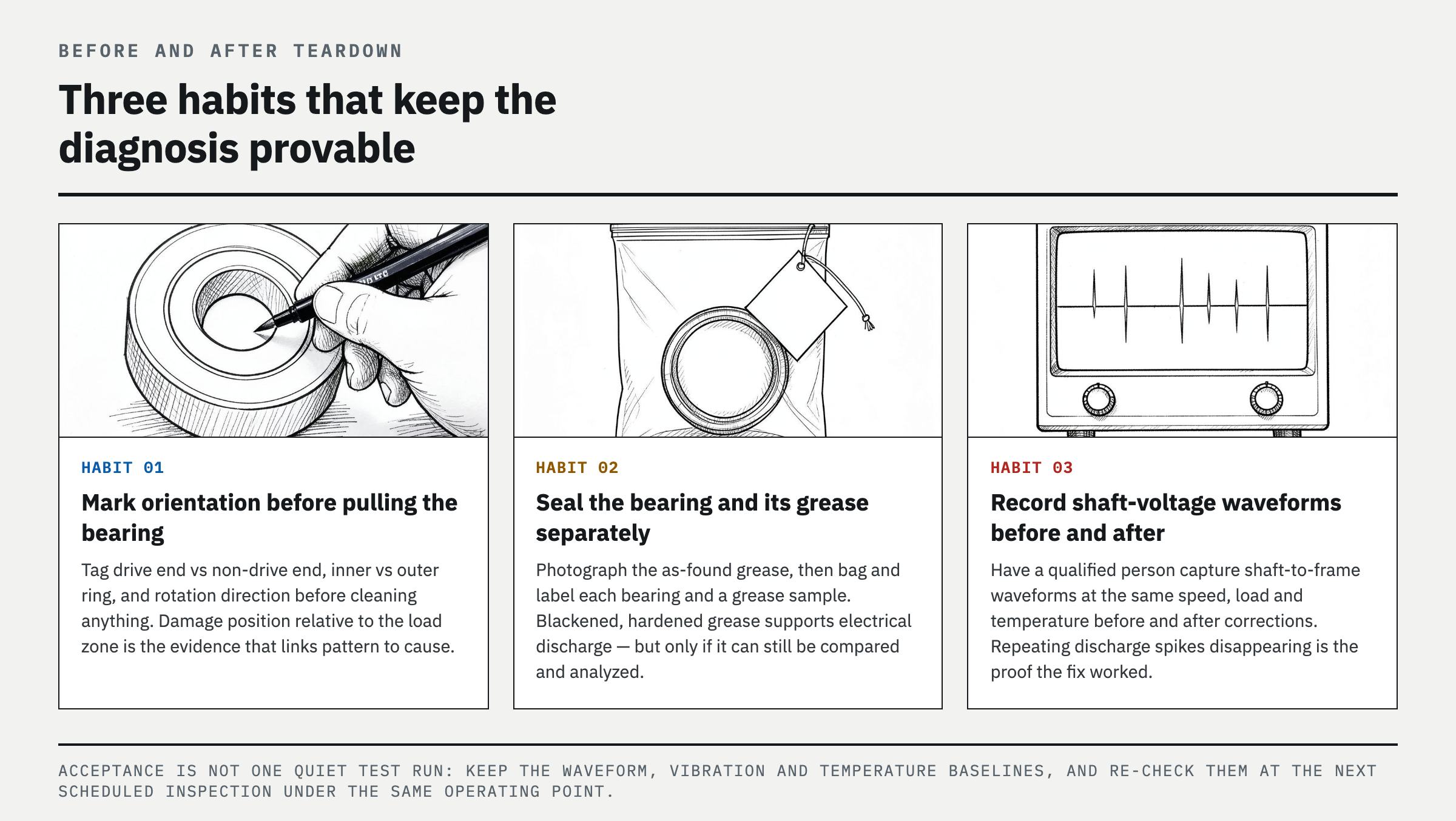
Gather the equipment single-line diagram, VFD and motor manuals, lockout/tagout (LOTO) equipment, a noncontact thermometer or fixed temperature sensor, a vibration meter, clean sample containers, lint-free wipes, and a magnifier. A metallurgical microscope or qualified analysis laboratory is required for confirmation. To check shaft voltage during operation, use an oscilloscope with suitable bandwidth and the shaft-voltage probe specified by the manufacturer. Do not use a single reading from a standard multimeter to judge fast discharge pulses.
Before shutdown, record how noise and vibration change with VFD frequency, speed, and load, and compare both bearing locations. During disassembly, photograph the raceways and grease before cleaning, and mark the drive end and non-drive end, inner and outer rings, direction of rotation, and load zone. Without orientation marks, critical evidence linking the damage location to the current path is lost.
Step-by-step diagnosis — narrow it down by pattern, microcraters, and current path
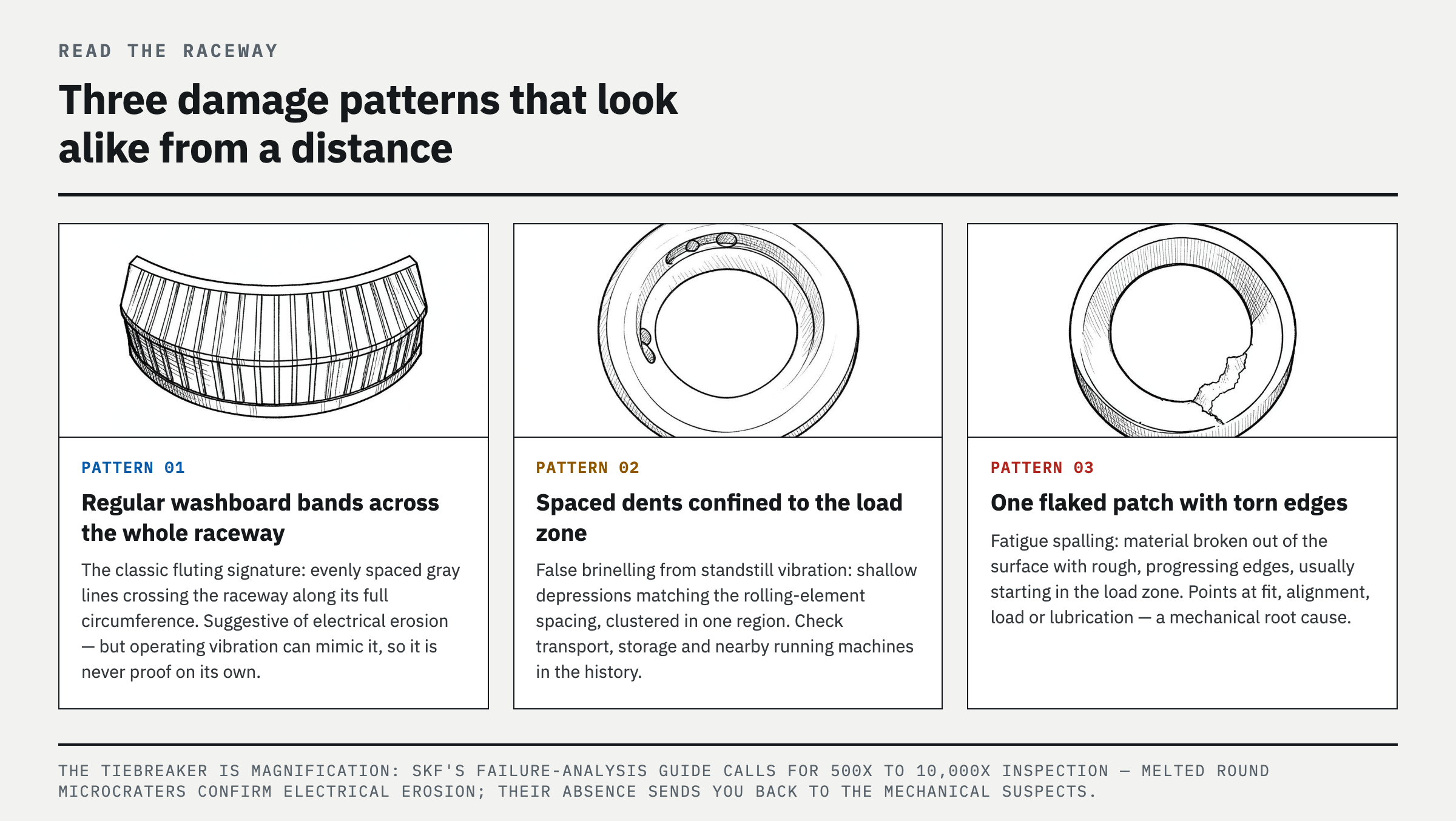
The first screening step is visual pattern recognition. Electrical fluting often appears as multiple regular gray, polished, or dark washboard bands across the raceway. The pattern alone, however, is not conclusive. False brinelling caused by vibration while stopped produces localized depressions matching ball spacing or lines matching roller contact, usually concentrated in a specific load zone. Overload brinelling centers on true indentations and material deformation. Fatigue spalling shows cracks, flaked material, and rough edges that indicate the direction of progression, while poor lubrication is dominated by smearing, scoring, discoloration, and signs of overheating.
The second step is magnified inspection of the cleaned raceways and rolling elements. Numerous round, melted microcraters extending across a broad gray, matte surface strongly support electrical discharge damage. SKF specifies 500× to 10,000× magnification for confirmatory inspection. Blackened, hardened grease is supporting evidence of discharge heating, but it can also result from overheating or contamination and is not diagnostic by itself.
The third step is to determine why current passes through the bearing in the installed system. Inspect high-frequency bonding between the motor frame and driven equipment, 360-degree shield termination at both ends of the motor cable, protective earth (PE) connections, insulated-bearing locations, and the contact surface and wear condition of shaft-grounding devices. A qualified technician should observe the shaft-to-frame waveform at normal operating temperature and representative speeds and loads to identify recurring discharge pulses. The waveform, operating conditions, manufacturer criteria, and before-and-after comparison matter more than one absolute voltage reading.
Common mistake — installing a grounding brush as soon as fluting is found
The most common mistake is assuming every regular groove is electrical fluting. SKF also warns that vibration during operation can create a washboard pattern, so omitting microcrater inspection can lead to a misdiagnosis. Conversely, the absence of visible grooves does not rule out electrical damage. Early VFD-related damage begins with microcraters that are difficult to see with the naked eye.
The second mistake is installing only a new bearing and a shaft-grounding brush while leaving the cable and bonding unchanged. If the high-frequency return path is poor, current may cross the coupling and move to gearbox or driven-equipment bearings. An insulated bearing does not eliminate current; it interrupts a specific path, so its location must be selected by evaluating the entire circuit.
The third mistake is cleaning the bearing before documenting its as-found condition or mixing the damaged bearing with scrap. Once grease condition, raceway load zone, and differences between the two bearings are lost, root-cause analysis becomes guesswork. Add pre-replacement photographs, orientation marks, and sample sealing to the work standard.
Verification — waveforms and trends must improve together after repair
Acceptance is not based on one test run in which the new bearing sounds quiet. Compare pre- and post-correction shaft-to-frame waveforms using the same probe location, representative speed and load, after the operating temperature has stabilized. Record bearing-discharge readings and vibration and temperature baselines. At scheduled inspection intervals, compare vibration spectra and temperature trends from the same locations. The corrective action is verified only when manufacturer limits and site baselines are both satisfied, recurring discharges are suppressed, and the trends remain stable.
Preserve the removed bearing and photograph the results after cleaning and magnified inspection. The electrical-fluting diagnosis is strongly supported if melted microcraters are confirmed and both discharge activity and degradation trends decline after the electrical path is corrected. If no craters are present and the damage corresponds only to the load zone and standstill vibration conditions, return to mechanical causes and investigate foundation vibration, belt tension, alignment, fits, and vibration during shipping or standby.
FAQ
How do you identify electrical fluting in a motor bearing?
Look for a regular gray washboard pattern on the cleaned raceway, then use a microscope to confirm numerous melted microcraters. Blackened, hardened grease and a shaft-to-frame discharge waveform during operation strengthen the diagnosis. A visual pattern alone cannot rule out vibration damage.
What does bearing fluting look like?
It usually appears as closely spaced, repeating gray or dark lines across the bearing raceway, forming washboard-like bands. Fluting is secondary damage that develops from microcraters, however, and operating vibration can create a similar pattern, so magnified inspection is required.
What is the difference between fluting and false brinelling?
Electrical fluting is characterized by broad repeating bands across the raceway and melted microcraters. False brinelling results from vibration while the bearing is stationary, producing localized contact marks in the load zone at rolling-element spacing; it also corresponds to vibration history during storage, shipping, or standby.
Will a shaft-grounding ring stop VFD bearing fluting?
It can be effective for certain capacitive shaft-voltage paths, but it is not a universal fix. If the cause is circulating current, poor high-frequency bonding, or incorrect cable shielding, one grounding device will not solve the problem. Review the cable, bonding, filters, and insulated bearings together according to the motor and drive manufacturers’ instructions.
References
- SKF, Bearing damage and failure analysis
- SKF Evolution, Prevention of electric erosion in bearings
- ABB, Technical guide No. 5 — Bearing currents in modern AC drive systems
- Fluke, Measuring motor shaft voltage discharges with Fluke MDA-550 Motor Drive Analyzer
- OSHA, 29 CFR 1910.147 — The control of hazardous energy (lockout/tagout)
Spotted an error or have a question about this guide? Email contact@fixtheplant.com — corrections are prioritized.