
Motors & Drives / Variable Frequency Drives
Why Does a VFD Trip on Overvoltage During Deceleration?
- Doc
- vfd-overvoltage-fault-on-deceleration
- Section
- motor-drives/vfd
- Revised
When a VFD decelerates a motor, the load does not lose its energy immediately. If rotor and machine inertia, an overhauling load, or material being unwound continues to drive the motor, the motor acts as a generator and returns energy to the VFD DC bus. If the rectifier cannot return that energy to the line and the braking circuit cannot absorb it, the DC bus voltage rises until the VFD trips on overvoltage to protect its power semiconductors. Instead of arbitrarily raising the trip threshold or repeatedly resetting the drive, record when the voltage rises and check both the amount of energy and its available dissipation path.
Key Specifications
| Specification | Value | Source |
|---|---|---|
| Deceleration-time adjustment | If increasing the deceleration time lowers the peak DC bus voltage and eliminates the trip, treat insufficient regenerative-energy handling capacity as the primary cause. Determine the allowable stopping time through process requirements and a machine risk assessment. | ABB ACS180 Hardware Manual, Resistor braking; Rockwell Automation PowerFlex 70/700 Reference Manual, Bus Regulation |
| Overvoltage-control operation | As the DC bus approaches the regulation setpoint, the controller may reduce the deceleration rate to limit the voltage rise, causing the actual deceleration time to exceed the programmed value. Feature names and operating conditions vary by model. | Rockwell Automation PowerFlex 70/700 Reference Manual, Bus Regulation; ABB ACS150 drives User's manual, overvoltage controller |
| Braking-resistor application | The braking chopper routes excess energy generated during deceleration to a resistor, where it is dissipated as heat. Determine resistance, peak braking power, and average duty using the selection tables and formulas provided by the VFD and resistor manufacturers. | ABB ACS180 Hardware Manual, Resistor braking |
| Overvoltage trip threshold | Do not apply a universal value because the threshold varies by voltage class and product family. Compare the displayed DC bus voltage directly with the trip threshold in the manual for the specific model. | Fault-code section of the applicable VFD manufacturer's hardware and firmware manuals |
Types & Variations
Extended deceleration ramp and overvoltage control
Reduces regenerative power or automatically extends deceleration time without additional hardware.
Use: Fans, pumps, and general conveyors with available stopping-time margin and intermittent deceleration
Braking chopper and braking resistor
Maintains short deceleration times by dissipating excess DC bus energy as heat in the resistor.
Use: Intermittent rapid-deceleration equipment whose repetition rate and average thermal load remain within the manufacturer's permitted duty
Regenerative drive and common DC bus
Returns regenerative energy to the power system or makes it available to other driven axes.
Use: Equipment with continuous regeneration or frequent stops, such as crane lowering systems, unwinders, and test stands
Maintenance Steps
- Record the fault and perform nonintrusive checks
Preserve the fault code and time of occurrence, and trend DC bus voltage, output frequency, speed reference, and current. Record maximum speed, load, direction, deceleration time, and stop frequency, and check input voltage and cooling condition.Do not place hands or test probes inside the enclosure while the equipment is operating. Prefer built-in monitoring functions and approved test points, and restrict access to rotating equipment and suspended-load areas.
- Isolate the setting with a controlled test
Back up the existing parameters, then gradually increase the deceleration time under safe test conditions and confirm whether overvoltage control is enabled. Compare peak DC bus voltage and actual stopping time for each test to distinguish a regenerative problem from a power-supply problem.Changing deceleration time or stop mode changes machine stopping distance and emergency-stop risk. Obtain process-owner approval and complete a risk assessment before making changes. Support vertical loads with an independent mechanical holding device.
- Inspect the de-energized braking circuit
Use the manufacturer''s schematic and selection data to verify the braking resistor nameplate, resistance, wiring, grounding, thermal contacts, and protective devices. Correct the cause of any open circuits, discoloration, cracking, or blocked ventilation, then replace damaged parts with properly rated components.Apply LOTO to the main power, control power, and external regenerative sources. Relieve stored pneumatic and hydraulic pressure, and dissipate or mechanically secure energy in rotating equipment and suspended loads. Do not assume the equipment is safe because an indicator is off. Wait for the manufacturer-specified discharge time, then verify absence of voltage with an approved instrument. Hazardous voltage may be present on the braking resistor and cables even when the chopper is off, and the resistor surface may be extremely hot immediately after operation.
- Verify under worst-case conditions
Restore all covers and guards, then perform repeated decelerations at maximum speed, maximum normal load, and the shortest approved cycle. Check DC bus voltage, stopping time, resistor temperature, thermal-contact status, and fault history, and retain the results as baseline data.For the first test, clear the restricted area and ensure an emergency-stop means is available. Do not arbitrarily increase the number of consecutive tests before temperature and voltage have stabilized.
Start by doubling the deceleration time
Before listing possible causes, one test can quickly divide the problem in half. Back up the current parameters. Under conditions where a longer stopping distance is safe, double only the deceleration time and run the same cycle that caused the fault: same maximum speed, same load, and same direction of rotation. Do not change any other settings. This single test helps distinguish between too much regenerative energy and a blocked energy-dissipation path.
There are three possible results. If the trip disappears and the peak DC bus voltage drops noticeably, the regenerative energy exceeds the available braking capacity. The decision then becomes whether to accept a longer deceleration time or maintain the stopping time by adding braking hardware. If the trip remains and the DC voltage immediately before the trip is nearly the same as before, deceleration is not the root cause. It is only the final trigger that pushes an already high voltage over the limit, so investigate the incoming power. Third, if the actual stopping time was already longer than the programmed deceleration time before the change, the overvoltage controller in ABB's ACS150 drives User's manual, or the Bus Regulation in Rockwell Automation's PowerFlex 70/700 Reference Manual, was already extending the ramp to control the voltage. In that case, increasing the setting may produce little noticeable change and indicates that no additional margin remains.
Changing the deceleration time or stop mode changes the machine stopping distance. On vertical axes and systems where collision avoidance or emergency stopping depends on stopping time, do not perform this test without first completing a risk assessment and obtaining approval from the person responsible for the process.
Three patterns revealed by the DC bus voltage trend
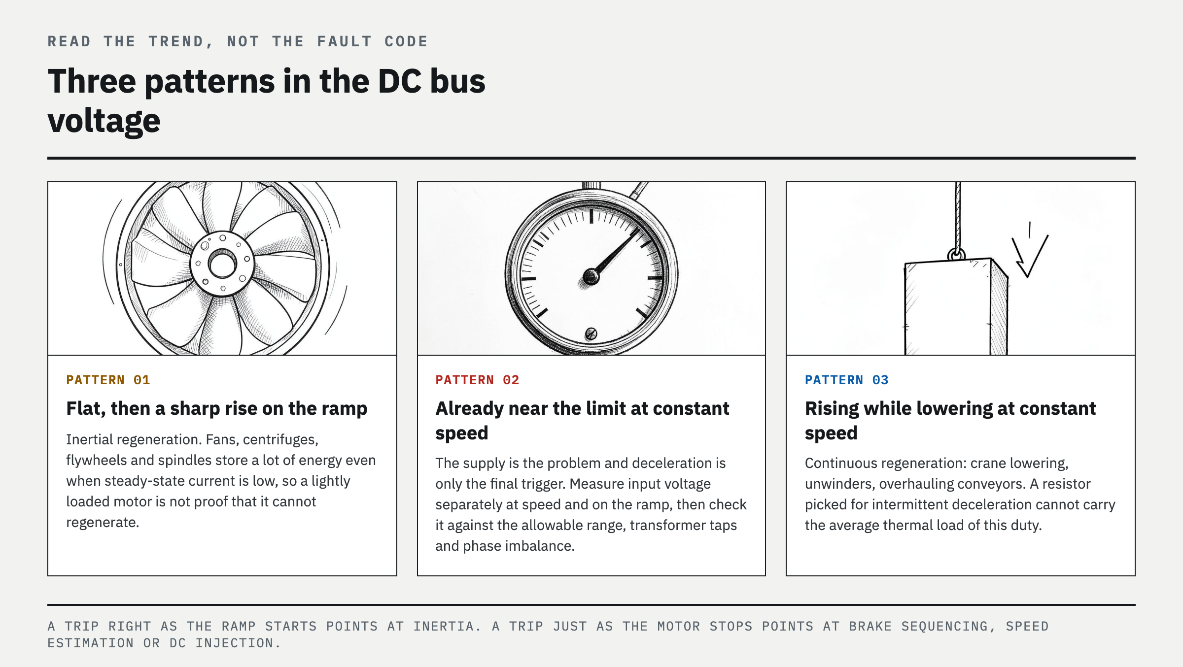
Trend the DC bus voltage, output frequency, speed reference, and output current on the same time base using the VFD monitor. Their waveforms help identify the cause. Use the displayed diagnostic values; do not open the enclosure and probe the DC terminals while the drive is operating.
Pattern 1 — The voltage is steady at constant speed and rises sharply as soon as deceleration is commanded. This is typical inertial regeneration. Large fans, centrifuges, flywheels, and high-speed spindles can store substantial energy even when steady-state current is low, so assuming that a lightly loaded motor cannot regenerate is often wrong. Pattern 2 — The voltage is already near its upper limit at constant speed, and only a small additional rise during deceleration causes a trip. This indicates a power-supply problem. Measure the input voltage separately at constant speed and during deceleration, then compare it with the manufacturer's allowable range, transformer tap settings, and phase-to-phase voltage imbalance. A fault that occurs only at night or during light utility loading is likely to follow this pattern. Pattern 3 — The voltage continues to rise while the machine lowers or unwinds at constant speed, not only during deceleration. Crane lowering, unwinders, and overhauling conveyors are continuously regenerative during normal operation. A braking resistor selected for intermittent deceleration cannot handle the average thermal load of this duty.
The trip timing also provides a clue. A trip immediately after deceleration begins points toward a short ramp and high inertia. A trip just before or after the motor stops calls for checking the mechanical-brake engagement sequence, unstable speed estimation, and DC injection braking settings. If multiple axes share the same power system or common DC bus, check whether regeneration from another axis overlaps the trip. If power-factor correction capacitors are connected on the VFD output, remove them first because that installation is inherently unsuitable for a VFD.
When the VFD trips even with a braking resistor installed
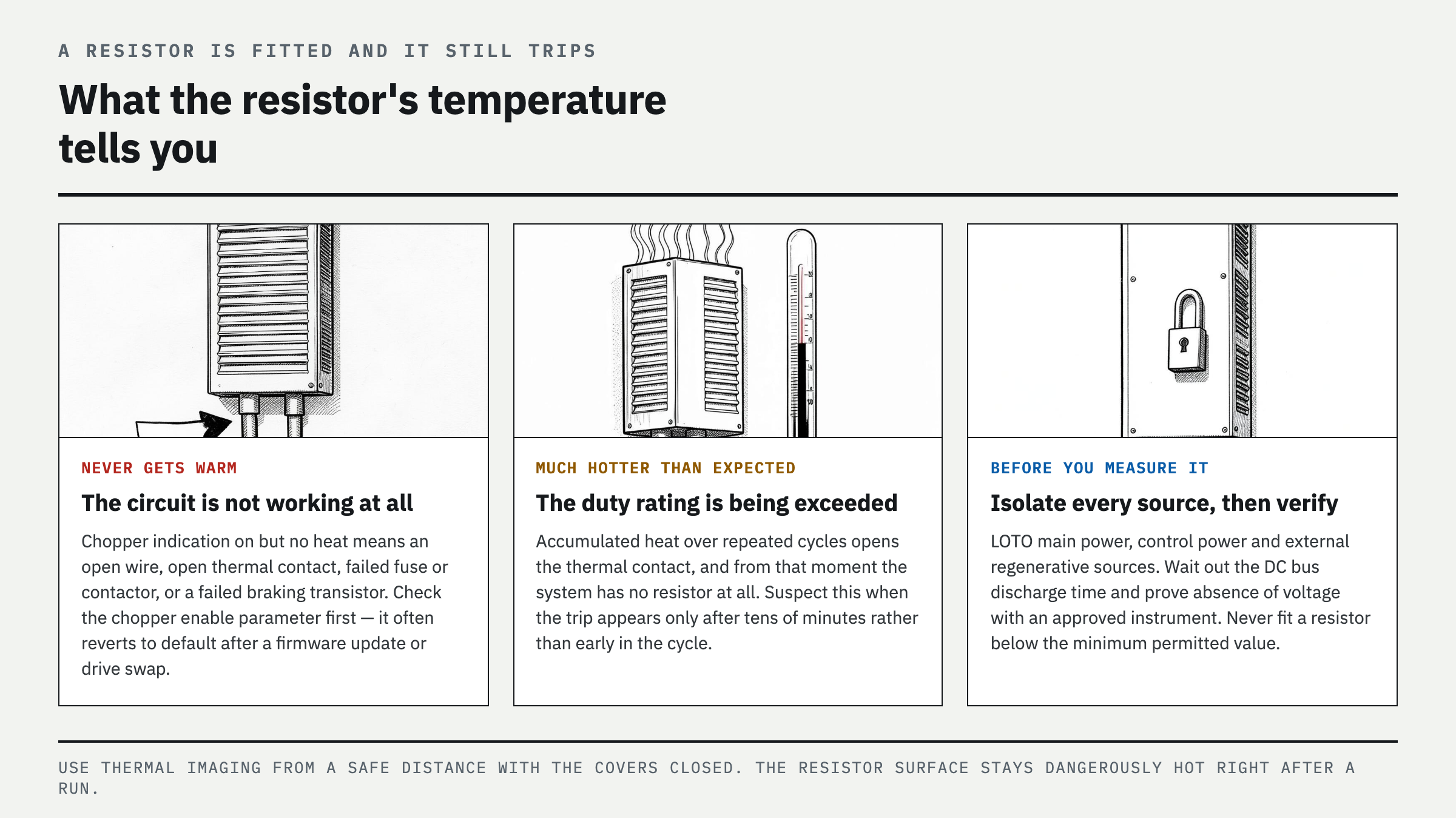
Most overvoltage trips on equipment that already has a braking resistor occur not because the resistor is undersized, but because the circuit is not actually operating. During a normal deceleration test, if the chopper-active indication or braking command turns on but the resistor does not heat at all, suspect an open wire, open thermal contact, failed fuse or contactor, or failed braking transistor. If the resistor becomes much hotter than expected, the duty rating is being exceeded.
Check the parameters first. Many models require the braking chopper to be enabled by parameter, and that setting commonly returns to its default after a firmware update or drive replacement. Next, compare the resistor nameplate value with the minimum resistance permitted for that VFD. Even with the correct resistance, accumulated heat during repeated cycles can open the thermal contact. From that point, the system effectively has no resistor, producing an intermittent trip. Check this pattern first if the fault occurs only after tens of minutes of continuous operation rather than early in the cycle.
Before measuring the resistor, apply lockout/tagout (LOTO) to the main power, control power, and all external regenerative sources. Observe the DC bus discharge indication and the manufacturer-specified waiting time, then verify absence of voltage with an approved instrument before accessing the circuit. Never connect a resistor below the minimum permitted resistance to eliminate the trip. Excessive chopper current can destroy the drive. When using thermal imaging, measure from a safe distance with the covers closed and the equipment operating normally.
What to choose when the stopping time cannot be increased
If the process permits a longer deceleration time, that is the least expensive and most reliable solution. Enable the overvoltage control, bus regulator, or automatic ramp-extension function on your drive — ABB's overvoltage controller, Rockwell Automation's Bus Regulation — then revalidate the machine safety distance using the new actual stopping time. A coast stop can also reduce regeneration on axes that do not require rapid stopping, but it cannot replace emergency-stop performance or a means of holding an overhauling load.
If the required stopping time must be maintained, proceed to sizing calculations. Four inputs are required: total inertia referred to the motor shaft, maximum speed, required deceleration time, and number of stops per hour. The first three determine peak braking power, while the fourth determines average thermal load. The design will fail if either requirement is ignored. Selecting only for peak power overheats the resistor during repeated cycles; selecting only for average load leaves the drive tripping during a single rapid deceleration. Compare the calculation with the braking resistor and braking unit selection tables in ABB's ACS180 drives Hardware manual, or in Yaskawa's Braking Unit CDBR and Braking Resistor Unit LKEB instructions, and comply with the minimum resistance, duty, overtemperature protection, cable, and clearance requirements.
The key distinction is whether regeneration is intermittent or continuous. When stops are infrequent and the resistor has time to cool between them, a braking chopper and resistor are the simplest solution. With frequent repeated stops or continuous energy return from vertical lowering or an unwinder, installing a larger resistor eventually becomes a heat-management problem. A regenerative front end or common DC bus is more appropriate. Whichever solution is selected, verify it through repeated decelerations at maximum speed, maximum load, and the shortest normal cycle. Record peak DC bus voltage, actual stopping time, resistor temperature, and thermal-contact status as baseline data. A single successful stop can miss cumulative heating. Raising the overvoltage trip level or bypassing protection is never a solution.
FAQ
Why does my VFD trip on overvoltage when stopping?
During the stopping ramp, load inertia or descending-load energy drives the motor as a generator, and the returned energy accumulates on the DC bus. First, check whether increasing the deceleration time eliminates the trip. If it does not, inspect for high input voltage, overvoltage-control settings, braking-resistor circuit faults, and continuously regenerative loads.
How do I fix VFD overvoltage during deceleration?
If the process allows it, increase the deceleration time and enable the VFD overvoltage controller or bus regulator. If the required stopping time must be maintained, calculate braking power and duty from inertia, speed, and stop frequency, then install the manufacturer-specified braking resistor or braking unit. Consider a regenerative drive for continuously regenerative loads.
Will a braking resistor stop VFD overvoltage faults?
If the VFD supports a braking chopper and the resistance, power, duty, parameters, and wiring are all correct, a braking resistor can reduce overvoltage caused by regenerative deceleration. However, adding a resistor alone will not correct high input voltage, a failed braking transistor, or inadequate thermal capacity for continuous regeneration.
Can I increase the VFD deceleration time to clear an overvoltage fault?
Yes. It is the first diagnostic test and often the simplest solution, but use it only where a longer actual stopping distance is safe. Do not arbitrarily extend it on vertical axes or systems where emergency stopping or collision avoidance depends on stopping time; review braking capacity and the safety circuit together.
References
- ABB, ACS180 drives Hardware manual — resistor braking (minimum brake resistance, brake thermal model)
- Rockwell Automation, PowerFlex 70/700 Adjustable Frequency AC Drives Reference Manual, Bus Regulation,
- ABB, ACS150 drives User's manual — overvoltage controller and fault tracing,
- Yaskawa, AC Drive Option Instructions — Braking Unit CDBR / Braking Resistor Unit LKEB,
Spotted an error or have a question about this guide? Email contact@fixtheplant.com — corrections are prioritized.