
Motors & Drives / Variable Frequency Drives
What Do VFD DC Bus Overvoltage Fault Codes Mean? (ABB, Rockwell, Yaskawa)
- Doc
- vfd-dc-bus-overvoltage-fault-codes
- Section
- motor-drives/vfd
- Revised
A VFD overvoltage indication does not mean the AC output voltage is too high. It means the DC link voltage between the rectifier and inverter sections has exceeded its protection threshold. ABB, Rockwell Automation, and Yaskawa use different codes for the same condition, and even within one manufacturer's product line, the code, trip threshold, and corrective action may vary by drive family and control program. In the field, do not search by fault code alone. Record the exact model number from the nameplate, the firmware or control program, and the drive's operating state when the fault occurred.
Key Specifications
| Specification | Value | Source |
|---|---|---|
| ABB ACS880 primary control program | 3210 — DC link overvoltage. The drive tripped because the DC link voltage was excessive. Follow the applicable manual to check overvoltage control, input voltage, deceleration time, and the braking chopper and resistor. | ABB, ACS880 primary control program firmware manual and ACS880-607LC hardware manual — fault 3210 DC link overvoltage |
| Rockwell Automation PowerFlex 40P | F5 OverVoltage — DC bus overvoltage. The official product information lists high input line voltage or transients and motor regeneration as possible causes. If regeneration is the cause, it directs the user to extend the deceleration time or install a dynamic braking option. Because that document does not state the trip-voltage value, verify it in the user manual for the exact model. | Rockwell Automation, PowerFlex 40P Adjustable Frequency AC Drive Product Information, publication 22D-PC001E-EN-P, February 2024 |
| Yaskawa E7·F7·P7 | oV / DC Bus Overvolt — DC bus overvoltage. The applicable product-family example in Yaskawa's official FAQ specifies 400 V DC or higher for the 208–240 V class and 800 V DC or higher for the 480 V class. The model-specific manual takes precedence. | Yaskawa, FAQ: OV — Fault Code Description, document DRV-5P4PKD (E7, F7, P7) |
| Initial interpretation by operating state | If the voltage rises during deceleration, check regenerative energy, deceleration time, and the braking path first. If the fault occurs at constant speed or on several drives simultaneously, prioritize high input voltage and power-line transients. Do not determine the cause from timing alone; verify it with trend data. | Combined guidance from ABB ACS880 fault tracing, Rockwell Automation PowerFlex 40P F5 corrective actions, and Yaskawa oV corrective actions |
Types & Variations
Regenerative overvoltage during deceleration
The DC bus is stable at constant speed but rises after a deceleration command, and extending the deceleration time tends to reduce the peak.
Use: Diagnosing high-inertia equipment or applications requiring rapid stops, such as fans, centrifuges, flywheels, and high-speed spindles
Line-side overvoltage or transient
The DC bus remains high at constant speed, or the fault occurs on several drives at once in correlation with time of day, transformer tap settings, or a shared power event.
Use: Investigating input line-to-line voltage trends, incoming power conditions, transformer tap settings, and switching transients
Inoperative braking path
Although a braking resistor is installed, energy cannot be dissipated because the chopper does not operate, wiring is open, a thermal contact is open, parameters are incorrect, or the allowable duty cycle is exceeded.
Use: Equipment that previously stopped normally but begins faulting after repeated operation, drive replacement, or parameter restoration
Maintenance Steps
- Preserve the fault code and operating conditions
Before resetting the drive, record the display, recent fault history, model number, input-voltage class, firmware, speed reference, output frequency, and internal DC bus monitor value. Verify the code in the official manual for the exact model and classify whether it occurred during deceleration, at constant speed, or with the output disabled.Do not open the enclosure and measure the DC terminals directly while the equipment is operating. Where possible, use the drive's isolated internal monitor and approved remote diagnostic functions.
- Separate input-power and deceleration causes
Compare the input line-to-line voltage and internal DC bus trends during constant-speed operation and deceleration. If permitted by the process and risk assessment, leave all other parameters unchanged, extend only the deceleration time, and retest at the same speed and load. Use the result to prioritize either a line-side problem or regenerative energy.Changing the deceleration time or stop mode changes stopping distance and can alter collision or falling-load hazards. Do not perform this test on vertical axes or personnel-safety functions without an approved risk assessment and independent mechanical support.
- Inspect the braking circuit in a de-energized state
Following the circuit diagram for the exact model, check the braking-resistor nameplate, allowable resistance, wiring, grounding, fuses and contactors, thermal contacts, chopper settings, and signs of deterioration. Replace damaged components with manufacturer-specified ratings.Apply LOTO to the main power, control power, common DC bus, and external regenerative sources. Fully relieve residual pneumatic and hydraulic pressure, and isolate or mechanically secure stored energy in rotating parts, springs, and suspended loads. Wait for the manufacturer-specified discharge time, then verify the absence of voltage with a suitable meter. Do not rely on extinguished indicator lights alone.
- Verify under normal worst-case conditions
After reinstalling covers and guards, perform repeated stops at the approved maximum speed and load and the shortest normal cycle. Record peak DC bus voltage, actual stopping time, resistor temperature, thermal-contact status, and fault history as baseline data.A braking resistor can remain hot enough after operation to cause burns or fire. Restrict access and comply with the manufacturer's clearance, ventilation, and overtemperature-protection requirements.
Fault-code conventions — same condition, different codes
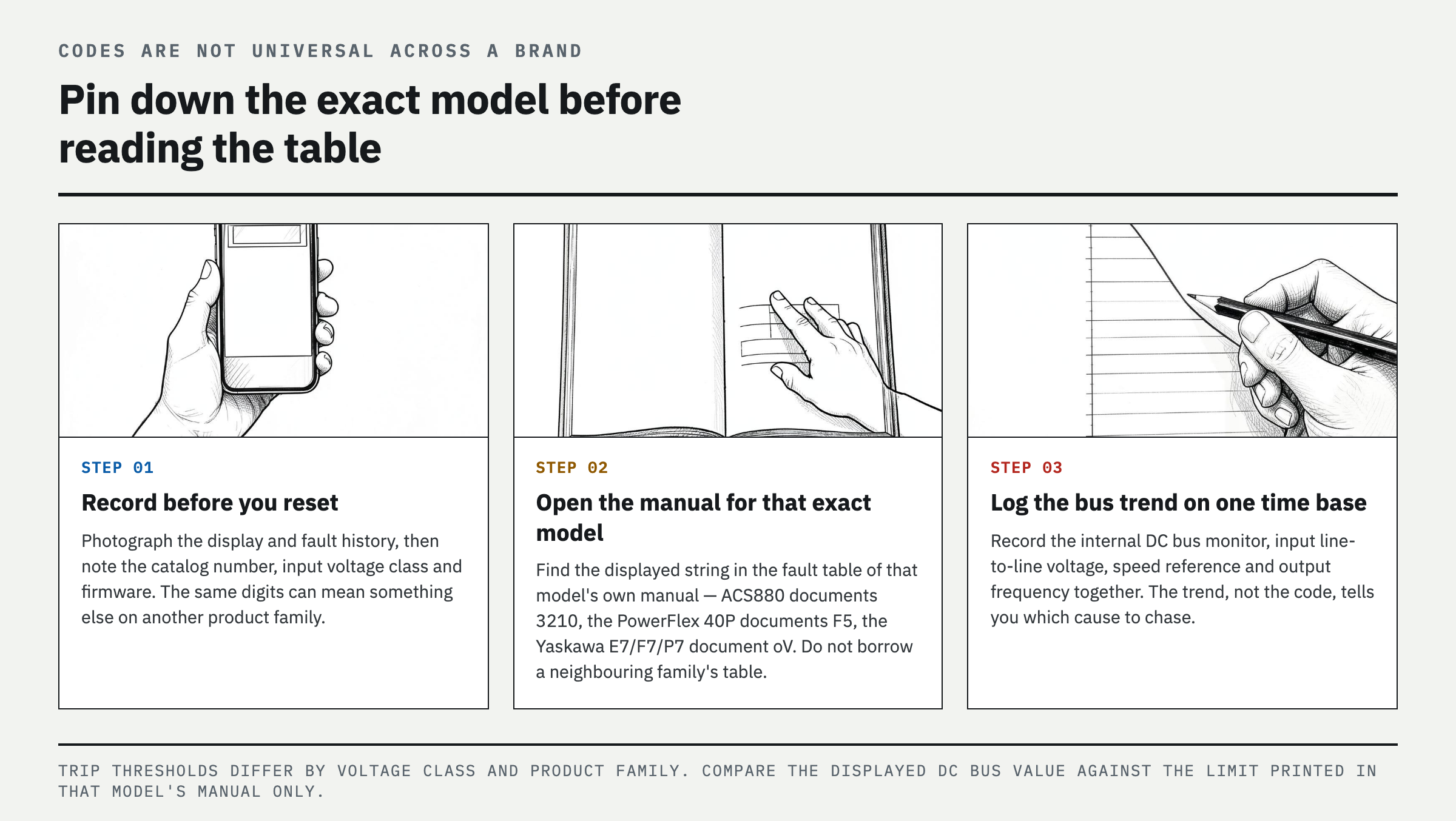
DC bus overvoltage describes the protection function; 3210, F5, and oV are the diagnostic indications used by specific product families. The ABB ACS880 primary control program identifies 3210 as DC link overvoltage, the Rockwell Automation PowerFlex 40P identifies F5 as OverVoltage, and the Yaskawa E7, F7, and P7 identify oV as DC bus overvoltage. Do not treat these three codes as universal code tables for their respective brands. Other PowerFlex generations or ABB control programs, for example, may use different names, numbers, or subcodes.
Trip thresholds also depend on the input-voltage class and model design. When a maintenance decision depends on a numeric value, do not mix values from online summaries. Use the drive nameplate ratings and the manual for that exact model. Values in the table below are examples stated in official documentation for specific product families; they must not be used as settings or test criteria for other models.
How to interpret the fault code
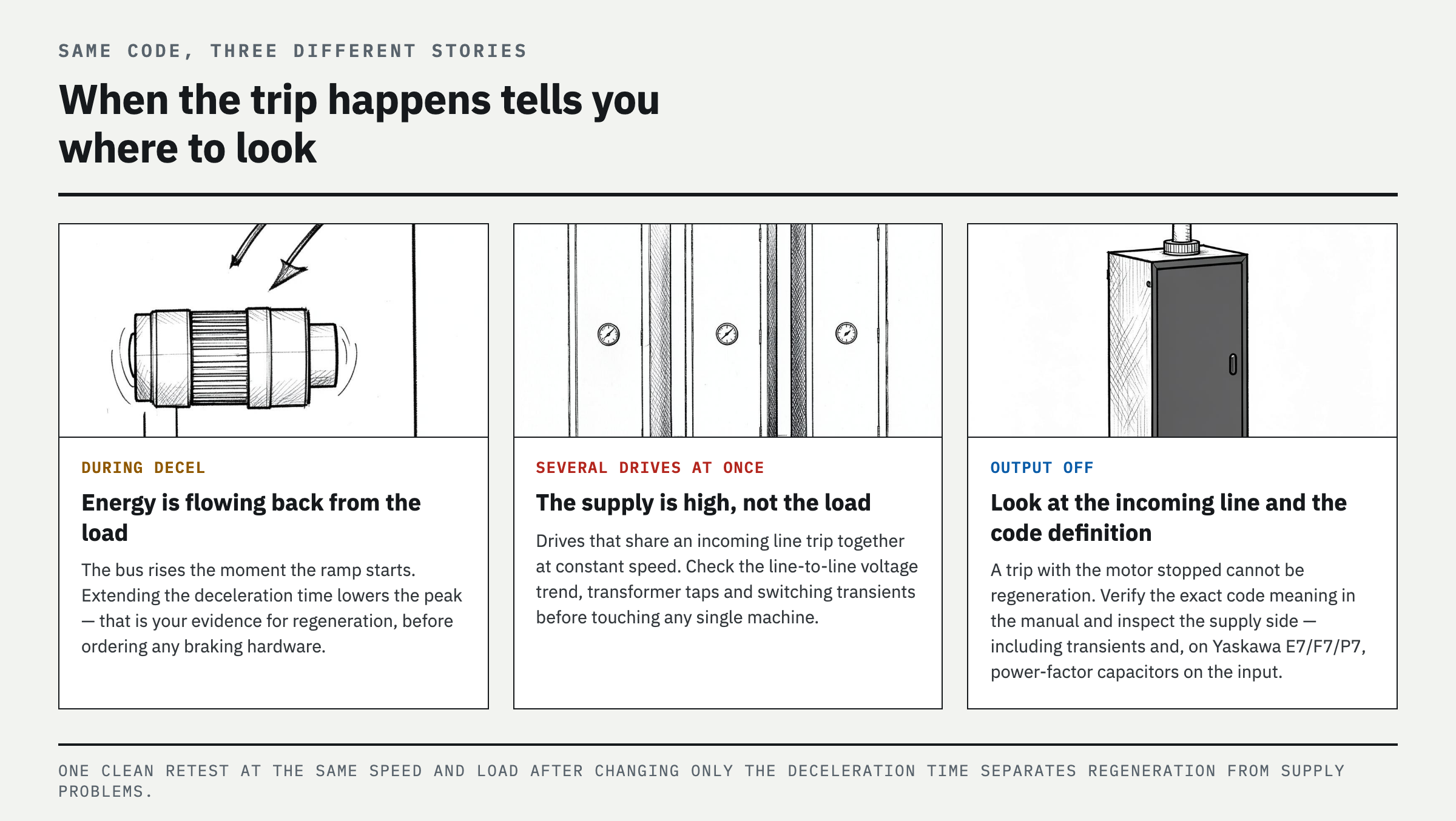
First, save a photo of the display and the fault history, then record the model number, input-voltage class, and firmware. Second, find the exact displayed text in the fault or alarm table for that model. Third, classify the operating state at the instant of the fault: decelerating, running at constant speed, before startup, or with the output disabled. If the DC bus rises as soon as deceleration is commanded, regenerative energy from the motor and load is the most likely cause. If the bus is already high at constant speed, or several drives fault at the same time, check high input voltage, transformer tap settings, and power-line transients first. If the fault occurs with the output disabled, prioritize the incoming power supply and the exact code definition over the deceleration ramp.
A common field mistake is ordering a braking resistor immediately after seeing F5 or oV. Under safe conditions, first log the drive's internal DC bus trend, input line-to-line voltage, speed reference, and output frequency on the same time base. If extending the deceleration time lowers the peak and eliminates the fault, that supports a regenerative-energy diagnosis. If it makes no difference, isolate high input voltage, transients, an open braking circuit, incorrect parameters, or model-specific causes identified in the manual.
Example — one conveyor drive repeatedly trips during deceleration
Assume a PowerFlex 40P runs normally at constant speed but trips on F5 immediately after a stop command. Of the two causes listed in the manual, this pattern points more strongly to motor regeneration and a short deceleration time than to high input voltage. If the process and the required stopping distance and safety constraints allow it, increase only the deceleration time and retest at the same speed and load. If the fault disappears, do not simply keep resetting the drive or change the protection threshold. Decide whether the process can accept the longer stopping time or whether a manufacturer-specified dynamic braking option must be sized.
Conversely, if several ABB ACS880 drives record 3210 while running at constant speed during lightly loaded nighttime hours, investigate the shared incoming voltage and transformer tap settings before individual motor inertia. If a Yaskawa E7, F7, or P7 reports oV and power-factor correction capacitors are connected at the input, check that configuration as directed by Yaskawa. The capacitor location and the consequences of removal must be reviewed by the responsible electrical engineer, and capacitors must not be installed on the VFD output without manufacturer approval.
Limitations and final diagnostic criteria
A fault-code definition is the starting point for diagnosis, not confirmation of the cause. Evaluate the timing of the fault, DC bus trend, input-voltage trend, actual deceleration time, and braking-chopper status together. A successful no-load test is less meaningful than repeated tests at the maximum normal speed and load and the shortest approved cycle. Even with a braking resistor installed, overvoltage will continue if the circuit is open, the thermal contact is open, the function is disabled by parameters, or the allowable duty cycle is exceeded. Raising the trip level, bypassing protection, or connecting a resistor below the minimum permitted resistance is not a solution.
FAQ
What does ABB fault 3210 DC link overvoltage mean?
In the ABB ACS880 primary control program, fault 3210 means the drive tripped because the DC link voltage exceeded the protective threshold. First determine whether it occurred during deceleration or at constant speed, then follow the manual for the exact model to check the input voltage, overvoltage control, deceleration time, braking chopper, and resistor.
What is PowerFlex F5 overvoltage fault?
On a PowerFlex 40P, F5 means the DC bus voltage exceeded its maximum value. Rockwell Automation lists high input voltage or transients and motor regeneration as causes. For regeneration, it recommends extending the deceleration time or installing the specified dynamic braking option. Consult the code table in the applicable manual for other PowerFlex families.
What causes Yaskawa oV DC bus overvoltage?
Yaskawa's official guidance for the E7, F7, and P7 lists high input voltage, an excessively short deceleration time, and power-factor correction capacitors on the drive input as major causes. On the exact model, check the fault timing and DC bus trend, then inspect the input circuit, deceleration settings, and energy-dissipation path in that order.
Can a braking resistor fix VFD DC bus overvoltage?
It can help when regenerative deceleration is the cause, the VFD supports a braking chopper, and the resistance, power rating, duty cycle, wiring, and settings are all correct. Adding a resistor alone will not correct high input voltage, transients, or a failed chopper. A regenerative drive may be more suitable for continuously regenerating loads.
References
- ABB, ACS880 primary control program firmware manual (3AUA0000085967) — fault tracing, fault 3210 DC link overvoltage,
- ABB, ACS880-607LC hardware manual — fault 3210 DC link overvoltage,
- Rockwell Automation, PowerFlex 40P Adjustable Frequency AC Drive Product Information, 22D-PC001E-EN-P,
- Yaskawa, FAQ: OV — Fault Code Description, DRV-5P4PKD,
Spotted an error or have a question about this guide? Email contact@fixtheplant.com — corrections are prioritized.