
Motors & Drives / Motor Starters & Overloads
Why Does the Overload Relay Trip When Motor Amps Are Normal?
- Doc
- overload-relay-trips-with-normal-amps
- Section
- motor-drives/motor-starters
- Revised
The statement "the amps are normal, but the overload trips" usually starts with a false assumption. A momentary clamp-meter reading on one phase does not measure the same thing as the heat accumulated by the relay over several minutes. This article first challenges that assumption, then systematically separates what the relay compared against when it tripped—its setting, CT configuration, and trip class—from heat sources unrelated to load current.
Key Specifications
| Specification | Value | Source |
|---|---|---|
| Relay Current Setting | Set the relay according to the motor nameplate full-load current and the relay manufacturer's instructions. The setting is not itself the trip current. Apply any correction for service factor or wiring configuration according to the specific product instructions and applicable requirements. | ABB, Thermal Overload Relays technical publication: https://library.e.abb.com/public/a9cd1c3f07dc1870852573a300738595/1SXU106043B0201.pdf |
| Trip Class (10 / 20 / 30) | Under IEC 60947-4-1, trip class specifies the maximum trip time at 7.2 times the set current. Based on the ABB TA…DU curves, Class 10 is 4–10 seconds, Class 20 is 6–20 seconds, and Class 30 is 9–30 seconds. Confirm the actual selection against the motor starting time and the applicable manufacturer's curve. | ABB, Thermal Overload Relays Tripping Class 20: https://library.e.abb.com/public/a9cd1c3f07dc1870852573a300738595/1SXU106043B0201.pdf |
| Response Relative to Set Current | The ABB TA…DU relay will not trip at 1.05 times the set current and will trip within two hours at 1.2 times the set current. This means current that appears "near nameplate" on a clamp meter can still cause a trip tens of minutes later. | ABB, Thermal Overload Relays Tripping Class 20: https://library.e.abb.com/public/a9cd1c3f07dc1870852573a300738595/1SXU106043B0201.pdf |
| Ambient Temperature Compensation Range | The ambient temperature compensation range for the ABB TA…DU thermal overload relay is -25°C to +55°C. At enclosure temperatures outside this compensation range, the trip time can change even at the same current. Use the data for the specific model when applying this value. | ABB, Thermal Overload Relays Tripping Class 20: https://library.e.abb.com/public/a9cd1c3f07dc1870852573a300738595/1SXU106043B0201.pdf |
Types & Variations
Bimetallic Thermal Overload Relay
Bimetal elements in all three poles model current-induced heating and are affected by the ambient temperature compensation range and heat conducted from the terminals.
Use: Common in simple across-the-line starters. If the phase currents are normal but the relay trips, first check the settings, terminal heating, mounting temperature, and cooling time.
Electronic Overload Relay
Uses current sensors and a thermal model for protection and may provide separate fault codes and adjustable values for phase loss, current imbalance, ground fault, and thermal capacity.
Use: When displayed current is normal, review the trip code, event history, CT ratio, and percentage of thermal capacity used to isolate the cause more quickly.
Electronic Relay with External CTs
CTs extend the relay's current range, so CT ratio, polarity, number of conductor passes, and parameter settings directly affect the reported current.
Use: For high-current motors or remote metering circuits, compare the CT configuration first when the actual clamp-meter current differs from the relay display.
Maintenance Steps
- Preserve Trip Information and Record Operating Data
Before resetting, record the trip indication, code, and time. A qualified worker using approved PPE and measurement procedures should record all three phase currents, start time, line-to-line voltage, and process load on the same timeline from startup through normal operation.Energized measurements present shock and arc-flash hazards. Follow the facility's electrical safety procedures and approach boundaries, and use meters and leads rated for the expected voltage and incident-energy environment.
- Isolate Energy and Verify Zero Voltage and Zero Residual Energy
After shutting down the equipment normally, apply LOTO according to the site procedure to the electrical disconnect and all associated mechanical, pneumatic, and hydraulic energy sources. Verify zero voltage using an approved method, stop and secure rotating parts, discharge stored electrical energy, and fully relieve residual pneumatic and hydraulic pressure.A stop button, open contactor, or PLC OFF command does not provide energy isolation. Verify proper operation of the tester before and after the test, and control gravity, springs, rotating inertia, and any residual pressure that can build again.
- Inspect and Repair Settings, Wiring, and Hot Spots
Compare the motor nameplate, actual connection, relay model and setting range, FLA, trip class, and CT ratio. Visually inspect the fuse holders, contactor, lugs, and motor terminals on all three poles, and apply the applicable manufacturer's torque procedure. Replace carbonized or discolored parts and parts with reduced spring tension using approved components.Simply retightening a heat-damaged terminal may leave damage to the contact surfaces and insulation. Do not bypass the relay or raise its setting without nameplate-based justification.
- Test the Restored Protective Function
Confirm that guards are installed and tools have been removed, then follow the formal LOTO removal procedure and start the equipment at no load or the minimum safe load. Check all three phase currents, acceleration time, relay thermal status, and trip history. Verify the output contact and trip circuit using the manufacturer's TEST function or approved test equipment.Automatic reset can cause an unexpected restart. Keep the relay in manual reset during testing and control access to hazardous areas around rotating equipment and the load. Conduct a separate risk assessment before enabling automatic mode.
Start by Challenging the "Normal Current" Reading
Most misdiagnoses start here. Measuring one phase for an instant with a clamp meter and seeing a value below the nameplate rating does not prove that the relay had no reason to trip. There are three reasons. First, the relay responds not to instantaneous current but to accumulated heating (I²t) over minutes. A 30-second load peak may flash across the meter display but remain in the relay's thermal model. Second, each pole's bimetal element heats independently in a thermal relay, while an electronic relay typically evaluates the highest phase current. The highest phase—not the average—is what matters. Third, an average-responding meter without true RMS capability reads low on circuits with distorted waveforms. Measure again. Measure all three phases over the same operating interval and use an instrument that records from startup through full speed, such as a logging clamp meter, power analyzer, or the maximum-current history in an electronic relay. Then calculate current imbalance as maximum deviation from the average ÷ average × 100. Until you have that number, there is no basis for calling the current normal.
The Relay's Reference Value May Differ from Yours
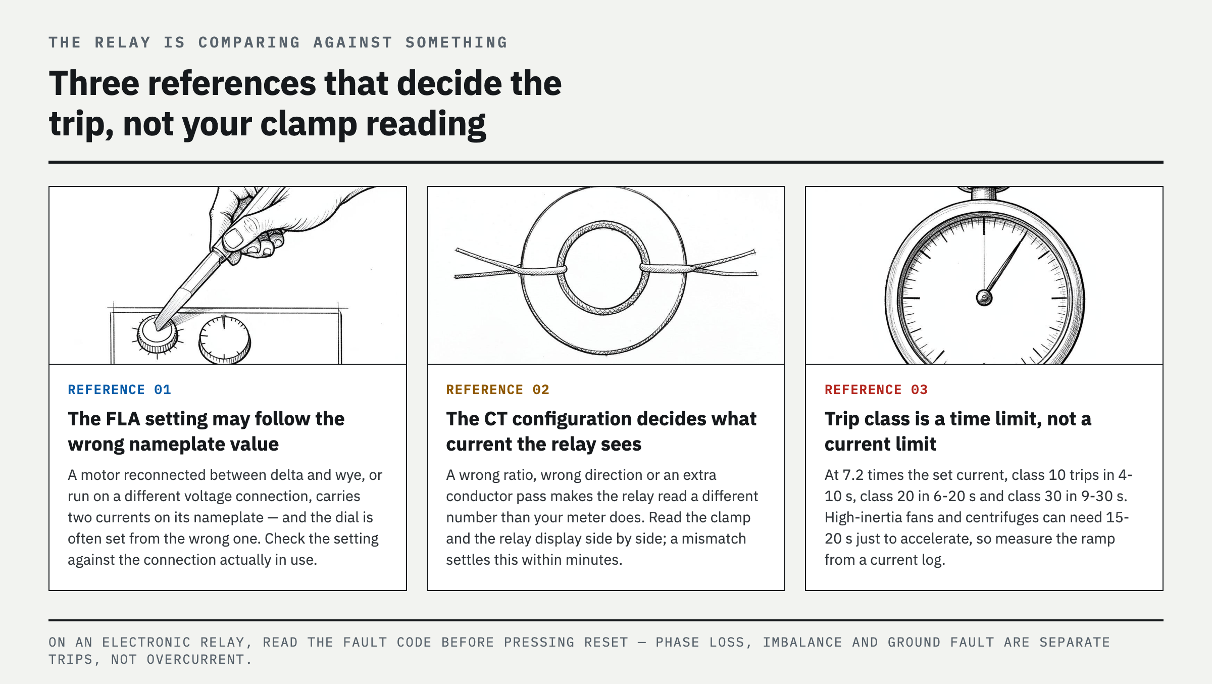
If the measured current truly is normal, next determine what reference the relay is using for comparison. ① FLA setting—Does the dial or parameter match the motor nameplate current? If the motor was reconnected between delta and wye or is operating on a different voltage connection, the nameplate may list two currents, and the relay is often set using the wrong one. ② External CT—If the CT ratio, number of conductor passes, direction, or parameter setting is wrong, the relay's current reading will differ from the measured value. Compare the clamp-meter reading with the relay display side by side; a mismatch identifies this problem within minutes. ③ Trip class—If running current is normal but the relay trips only during startup, the issue is time rather than running current. Trip class specifies the maximum trip time at 7.2 times the set current. Class 10 is 4–10 seconds, Class 20 is 6–20 seconds, and Class 30 is 9–30 seconds. High-inertia loads such as large fans, centrifuges, and flywheels can take 15–20 seconds just to accelerate. Measure acceleration time from the current log, not with a stopwatch, and compare it with the trip-class curve. ④ With an electronic relay, the trip may not have been caused by overcurrent at all. Phase loss, imbalance, and ground fault appear as separate fault codes. Read the code before pressing reset.
How the Relay Can Heat Up Even When Current Is Normal
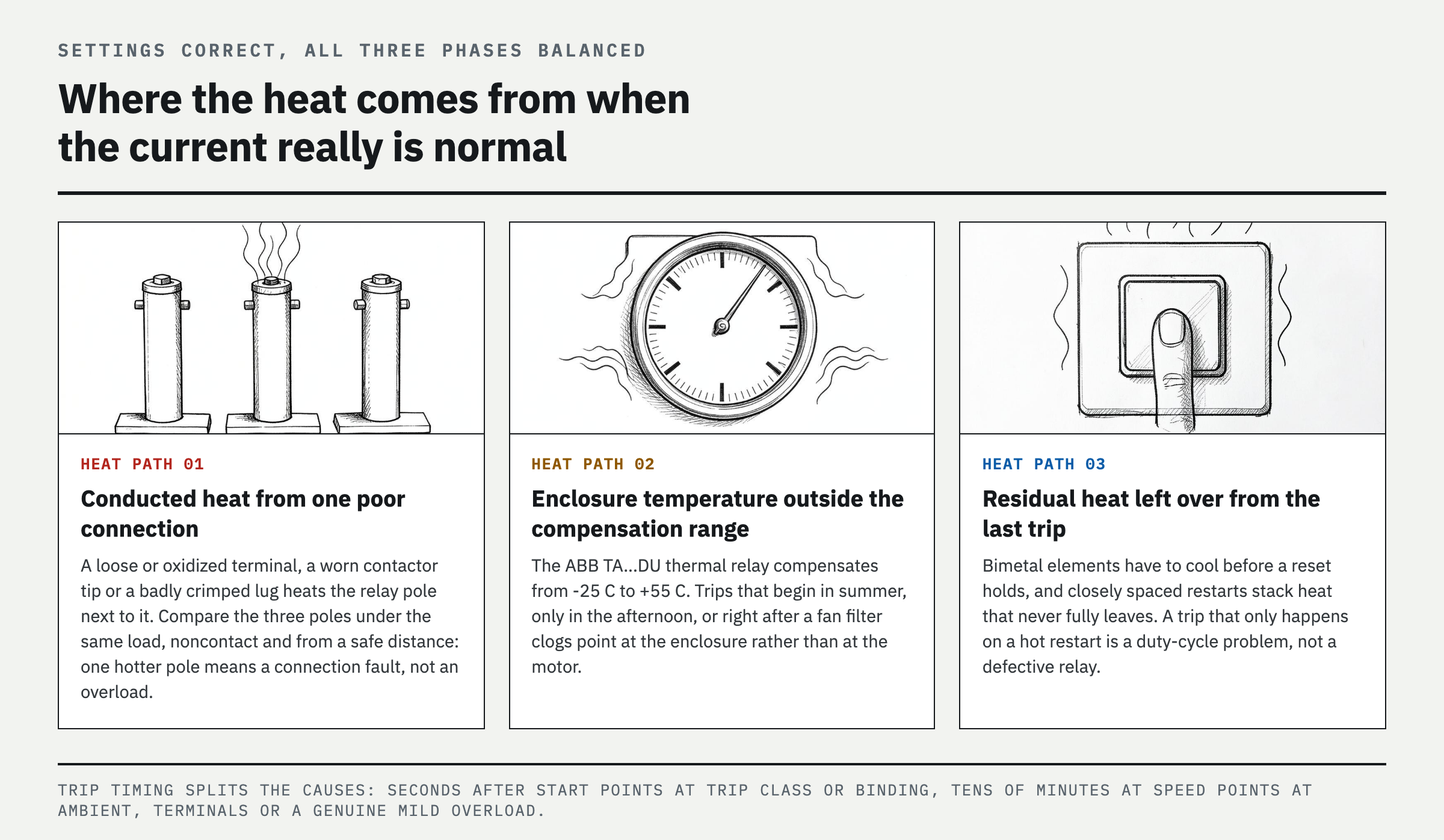
If the settings are correct and all three phase currents are balanced, heat may be reaching the relay's bimetal elements from a source other than load current. The first path is conducted heat. A loose or oxidized terminal, worn contactor main contact, or poorly crimped lug creates heat through contact resistance, and that heat transfers directly into the adjacent relay pole. Compare the temperatures of all three poles. Under the same load, one noticeably hotter pole points to a connection problem rather than current (make only a noncontact relative comparison, without approaching energized parts). Also remember that the relay will not trip at 1.05 times the set current but will trip within two hours at 1.2 times the set current, based on the ABB TA…DU relay. Current slightly above the nameplate rating may look "normal" on a clamp-meter display but still produce a trip tens of minutes later. The second path is ambient temperature. A bimetallic relay is affected by the temperature inside the enclosure and has a specified compensation range. Suspect this cause if trips occur only in summer, only in the afternoon, or only after a fan filter becomes clogged. The third factor is cooling time. After a thermal relay trips, its bimetal elements must cool before it can reset, and closely spaced repeated starts accumulate residual heat. Trip timing helps separate the causes. A trip within seconds of startup points to trip class or mechanical binding; a trip after tens of minutes at normal speed points to ambient temperature, terminal heating, or a genuine mild overload; and a trip only when restarting immediately after shutdown points to cooling time and start frequency.
What to Do After Confirming the Cause—and What Never to Do
Once the cause is identified, the corrective action is straightforward. Correct an improper FLA setting, CT configuration, or motor connection according to the nameplate and manufacturer's instructions, and document the final settings. For phase imbalance or phase loss, do not stop after replacing a fuse. Trace the circuit through the fuse holder, contactor main contacts, cable lugs, and motor terminal box. Replace heat-damaged terminals because retightening alone will not restore them. If start time is the issue, first correct driven-equipment binding, low voltage, or excessive load. If acceleration is still long, select a trip class that matches the measured acceleration time using the motor-starter coordination table. Restore enclosure ventilation, filters, and mounting clearances to the product's allowable conditions. Suspect the relay itself only after all these items have been verified, and replace it with an approved part of the same range and rating. There is one thing never to do—raise the dial one increment after every trip. That hides a poor connection or mild overload while removing thermal protection from the motor windings. Jumpering the protective contact is even less acceptable.
FAQ
Why does my motor overload keep tripping with no load?
Even at no load, heat can accumulate because of phase loss, low voltage, an incorrect motor connection, a binding bearing or brake, frequent starts, a low FLA setting, or heat at a relay terminal. Record all three phase currents and acceleration time together. Compare operation before and after disconnecting the motor from the mechanical load only when the separation can be performed safely.
Can a bad overload relay trip at normal current?
Yes, but a defective relay should be the last conclusion. First check the trip indication, FLA and CT settings, three-phase imbalance, heating at the contactor and terminals, ambient temperature, and start cycle. Replace the relay with an approved unit of the same rating only when the input conditions are normal and the malfunction can be reproduced using the manufacturer's test procedure.
How do I know if a motor overload relay is set correctly?
Confirm that the motor nameplate current falls within the relay's adjustment range, then account for the actual motor connection and any external CT ratio and set the relay according to the manufacturer's instructions. Do not match the dial value to the normal current shown on a handheld meter or raise it in response to repeated trips.
Can phase imbalance trip an overload relay even if average amps are normal?
Yes. An average hides the high and low phases. A thermal relay may respond strongly to imbalance during phase loss, while an electronic relay may trip on the highest phase current or a separate imbalance threshold. Compare all three phase readings at the same operating point and inspect the contactor, fuses, and terminals as well.
References
Spotted an error or have a question about this guide? Email contact@fixtheplant.com — corrections are prioritized.