
Hydraulics & Pneumatics / Pneumatic Cylinders & Actuators
Why a Stopped Pneumatic Cylinder Drifts
- Doc
- pneumatic-cylinder-drift-when-stopped
- Section
- hydraulics-pneumatics/pneumatic-actuators
- Revised
A stopped pneumatic cylinder isn't locked the way a brake locks a shaft. Even when a valve traps air on both sides, that air is compressible, valves and fittings and seals all have real-world leakage, and the rod-side and head-side effective areas differ. So the first job is separating a slow creep that shows up seconds after the stop command from a sudden jump right at the command, and deciding whether this is a position-holding problem or a dangerous load-holding problem. Swapping the seal kit first is a common mistake in the field — if the real cause is valve spool leakage or common-exhaust back-pressure, a brand-new cylinder will drift exactly the same way.
Key Specifications
| Specification | Value | Source |
|---|---|---|
| Continuous air flows from the opposite port when one chamber is pressurized | Suspect piston seal bypass or bore damage first. Support the load, confirm with the manufacturer's test procedure, then inspect the seal and bore together. | Manufacturer cylinder service/rebuild literature (e.g., Parker Hannifin, SMC, Festo technical guides) — internal-leakage test practice |
| No leakage in the cylinder's own test, but the assembled circuit still drifts | Investigate the directional control valve, manifold gaskets, speed controllers, fittings and tubing for leaks, or a valve center-position issue. | Manufacturer cylinder service/rebuild literature (e.g., Parker Hannifin, SMC, Festo technical guides) — internal-leakage test practice |
| Slow movement toward the load direction even with a closed-center valve | A closed center is not a safety lock. Evaluate valve/plumbing leakage, the compressibility of trapped air, the effective-area difference between chambers, and external force together. | ISO 4414:2010, Pneumatic fluid power — General rules and safety requirements for systems and their components |
| Small movement after stopping even with a locking cylinder | Check the product's lock direction, static holding force, allowable movement, and circuit conditions. For example, SMC's CLK2 specifies up to 1 mm of movement in the lock direction under external force and pressure loss. | SMC, CLK2 Series Clamp Cylinder with Lock catalog, Specific Product Precautions |
| Circuit needs to be opened for servicing | Don't trust a control stop button alone — isolate, lock, and tag all energy sources, bleed residual pressure, and verify no re-accumulation and a zero-energy state. | OSHA, 29 CFR 1910.147(d)(5)-(6), Control of Hazardous Energy |
Types & Variations
Standard double-acting cylinder with a 3-position valve stop
Traps, exhausts, or pressurizes both chambers depending on the valve's center state, with no separate mechanical lock.
Use: Use for short intermediate stops where drift within process tolerance is acceptable. Never use alone as fall protection or personnel protection.
Pilot check valve or a valve mounted close to the cylinder
Reduces the air-escape path and trapped volume near the cylinder, holding position tighter than a standard valve alone.
Use: Apply when improving process position-holding performance, after reviewing the circuit manufacturer's minimum pilot pressure and exhaust/emergency conditions.
Cylinder with a built-in load lock or brake, or a mechanical stop
Limits rod or load movement with a mechanical element, not air pressure alone — lock direction and static/dynamic ratings vary by product.
Use: Use after a risk assessment for vertical axes and hazardous loads. Always confirm with manufacturer documentation whether the lock is safety-rated or static-holding only.
Maintenance Steps
- Support the load and isolate energy
Fix the load with independent mechanical support — rated blocks, pins, jacks — so nothing drops or a pinch point closes even if the cylinder moves. Identify every energy source at the equipment — electrical, pneumatic, gravitational, spring — and apply lockout/tagout per site procedure.Valve neutral or an e-stop is not energy isolation. Don't get under a vertical load, and mechanically support the load before bleeding air.
- Bleed residual pressure and verify zero energy
Cut supply with a lockable shutoff/vent valve and bleed residual pressure from both chambers and any accumulator through an approved path. Confirm the gauge reads zero and verify no restart and no re-accumulation using a site-approved method such as an operation test.A system gauge can read zero while pressure remains trapped in the cylinder because of a check valve, a blocked muffler, or a trapped chamber. Don't loosen a port to bleed residual pressure.
- Check external leaks and pressure trend
With guards and PPE restored for the test, check for external leaks at fittings, tubing, the valve, and the cylinder using an approved leak-detection fluid or instrument, and log both port pressures over time under the same conditions.Run pressurized diagnostics as a separate approved test procedure, not the LOTO service state, and keep people out of the hazard zone. Don't hunt high-pressure leaks by hand or by ear.
- Isolate the diagnosis between cylinder and valve
With the load still supported, run the manufacturer's cylinder bypass test and valve leakage test separately. Compare opposite-port outflow, valve exhaust outflow, and pressure drop to confirm the fault boundary.Don't disconnect a pressurized port or hose. Follow the model's service manual for test pressure, connection sequence, and allowable leakage — don't apply an arbitrary universal number.
- Verify function and safety after the repair
Repair or replace the root-cause part per manufacturer instructions, and adjust alignment, speed, and end-of-stroke impact. Re-measure stop position and both port pressures under normal and maximum expected load and supply variation, and verify any safety-holding device separately.Don't put a person under the load to verify a load lock or mechanical stop. Confirm pressure balance on both sides and load support before releasing the lock to prevent sudden movement.
Check the symptom — when, which direction, and how consistently it moves
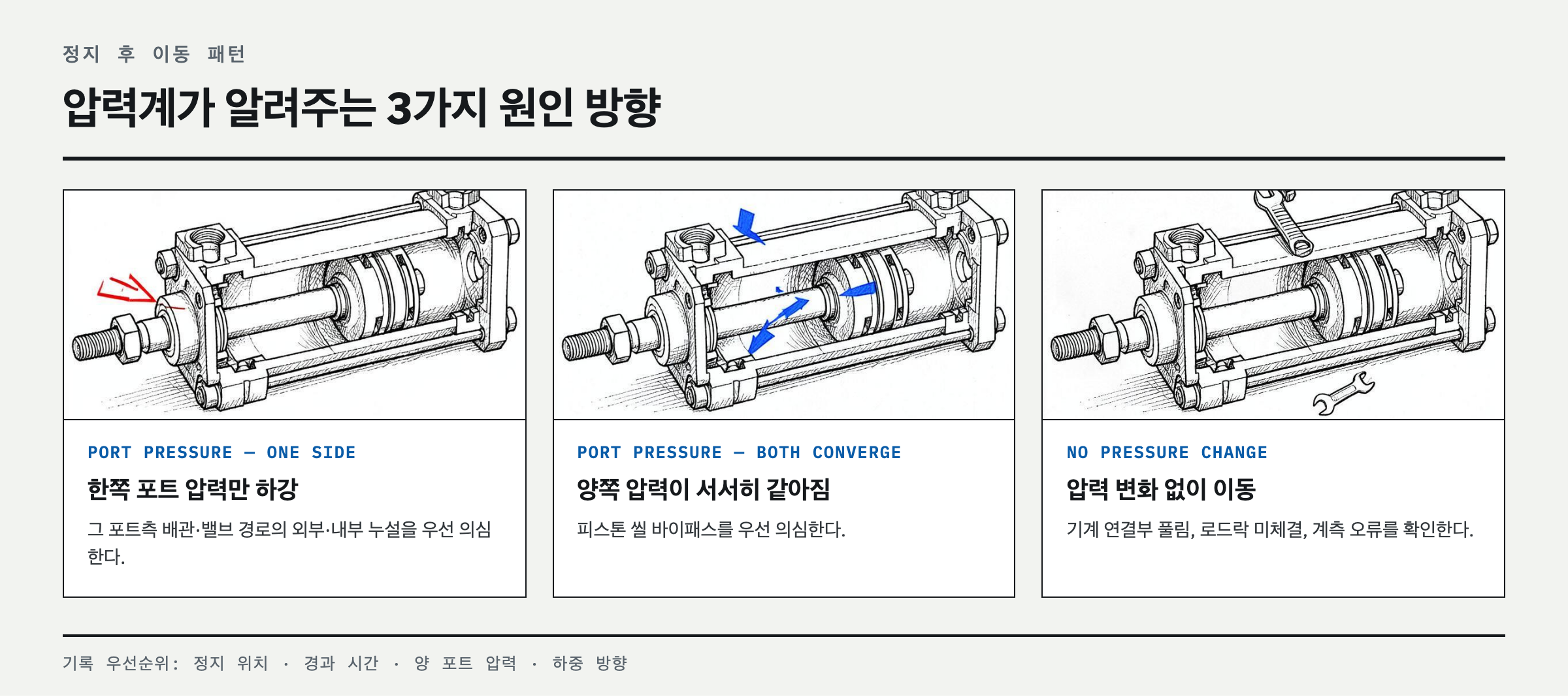
Mark a baseline on the rod and the fixed structure, then log the instant of movement right after the stop command, any slow creep some time later, and any movement after power or supply air is cut, as three separate cases. Repeat at the same position, load, and temperature while watching both port pressures at once. If only one side's pressure drops, suspect external or internal leakage in that side's plumbing or valve path first; if both pressures slowly converge while it moves, suspect piston seal bypass first. If a vertical axis sags with no pressure change at all, also check for a loose mechanical connection, a load lock that never engaged, or a measurement-point error. When hunting external leaks with soap solution, use an approved leak-detection fluid and don't spray it on electrical components. Don't log displacement alone — record stop position, elapsed time, both port pressures, supply pressure, and load direction together on one sheet, or an intermittent fault won't show up.
Rank the causes — in the order they actually show up in the field
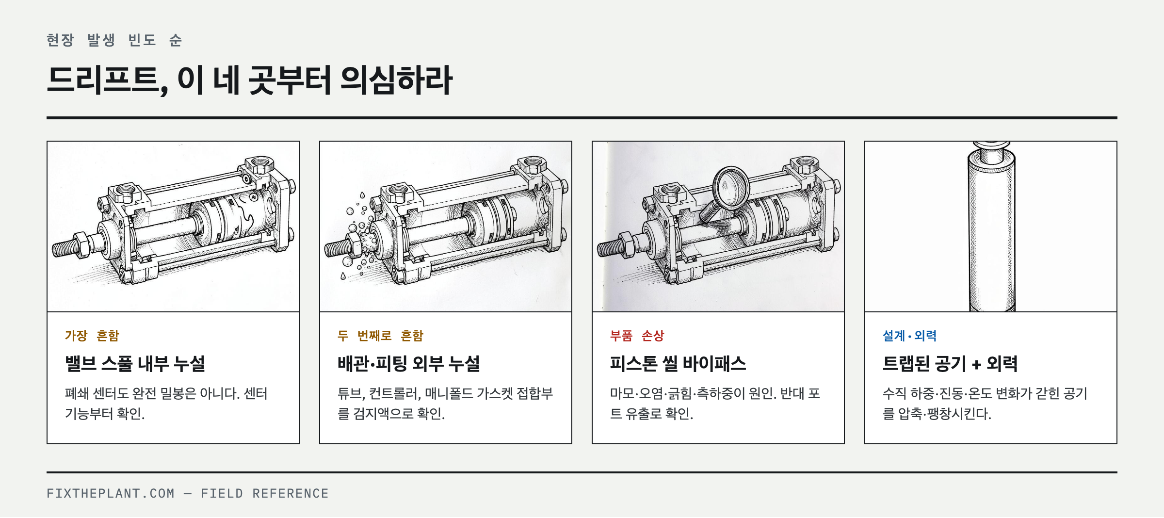
First is internal leakage across the directional control valve's spool and seat, or a misunderstanding of what the center position actually does — a closed center is not a complete seal or a safety lock, and exhaust-center or pressure-center valves deliberately change the port state. Second is external leakage at tubing, fittings, speed controllers, quick-exhaust valves, and manifold gaskets. Third is piston seal bypass from wear, contamination, scoring, or side loading. Fourth is the valve never fully returning to center — from supply pressure fluctuation, common-exhaust back-pressure, a solenoid that stays partially energized, or insufficient pilot pressure. Fifth is a vertical load, spring force, an eccentric linkage, vibration, or temperature change compressing or expanding the trapped air. Last is insufficient cylinder sizing margin, the area difference between rod side and head side, a damaged load lock, or a poorly configured check-valve circuit.
Diagnose by cause — separate the boundaries before you swap parts
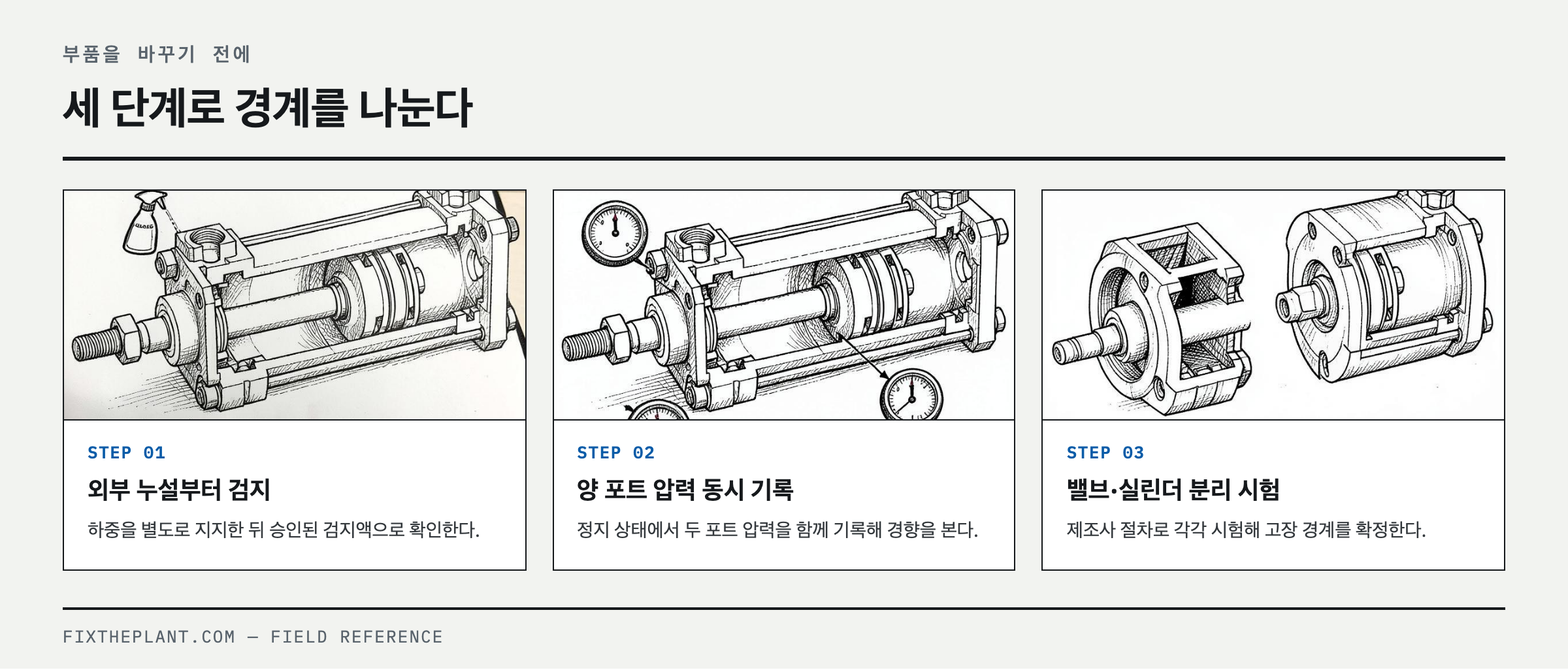
First, with the load independently supported, check for external leaks using an approved procedure. Next, log both port pressures at the same time while stopped. If a specific port's pressure disappears toward the valve, disconnect the valve and the plumbing between them to isolate it. For the piston seal test, follow the manufacturer's procedure — pressurize only one chamber to a limited test pressure and watch the opposite port for continuous outflow. Disconnecting the opposite port and watching for leakage, then looking elsewhere in the circuit if there's none, is standard field diagnostic order. Never check this by suddenly loosening a port while the cylinder can still move. If swapping in a verified valve of the same spec makes the symptom disappear, the valve is strongly implicated. If it only moves when supply is cut, look at the residual-pressure exhaust path and check-valve orientation; if it's worst over a specific stroke section, check for a bent tube, a scored bore, or misalignment.
Fix it — repair the leak path and match the stop method to the application
For external leaks, re-cut the damaged tube end cleanly and replace with correctly sized fittings and seals. For internal valve leakage or poor center return, correct contamination and pilot conditions and repair or replace the valve within manufacturer tolerances. If piston bypass is confirmed, inspect the bore and rod alignment too before servicing with the specified seal kit or replacing the cylinder — replacing only the seal while leaving side loading in place brings the problem right back. If the process only needs a short hold, a circuit-manufacturer-approved pilot check valve or a valve mounted close to the cylinder can reduce trapped volume, but compressibility means this is never an absolute position lock. For vertical axes, presses, clamps, and any zone where a person enters, apply a load lock, brake, counterbalance, or mechanical stop rated for the load, direction, and impact conditions, and verify it with a risk assessment.
Prevent recurrence — separate the drift-tolerance spec from the safety-holding spec
Write the stop position, observation time, load, supply pressure, temperature condition, and allowable movement together into the equipment acceptance criteria. Don't copy a universal number — set the limit from process tolerance and a risk assessment. Add both port pressure trends, abnormal exhaust noise, rod contamination, and fitting damage to shift checks, and manage filter differential pressure, drains, and air quality on the component manufacturer's schedule. Keeping a pressure-versus-time record from before and after a valve or cylinder replacement cuts down on unjustified parts swapping. A common mistake is closing the meter-out excessively to slow the speed, which creates high back-pressure and seal wear — recheck stop behavior after any speed adjustment too. Distinguish whether a load lock is a static-holding device or a dynamic-braking device, and tie the manufacturer's allowable load, direction, and circuit conditions into the work standard.
FAQ
Why does my pneumatic cylinder move after the valve is centered?
Even with the valve centered, internal leakage through spool clearance, fitting leaks, piston seal bypass, and the compressibility of trapped air can shift the force balance. First confirm what the valve's center function actually does, compare both port pressure trends, then diagnose the cylinder and valve separately.
Will a closed-center valve stop a pneumatic cylinder from drifting?
It can reduce drift, but it doesn't guarantee a complete lock or safe load-holding. Real valves and seals leak, and air is compressible. Set the allowable process movement by testing, and use a rated load lock or mechanical stop separately for any fall or pinch hazard.
How do I test a pneumatic cylinder for internal leakage?
After independently supporting the load and completing LOTO and residual-pressure bleed, pressurize one chamber to a limited level per the manufacturer's procedure and measure continuous outflow at the opposite port. Never test by loosening a pressurized connection, and follow the cylinder's seal design and model-specific service criteria for allowable leakage.
Can a pneumatic cylinder safely hold a vertical load when air is off?
A standard cylinder and directional control valve alone can't be considered safe. The load can drop if residual pressure bleeds off or a seal leaks after supply is cut. Based on a risk assessment, apply an independent holding means rated for gravity loads — a load lock, brake, or mechanical pin/block.
References
- SMC, CLK2 Series Clamp Cylinder with Lock, Specific Product Precautions
- ISO 4414:2010, Pneumatic fluid power — General rules and safety requirements for systems and their components
- OSHA, 29 CFR 1910.147, The control of hazardous energy (lockout/tagout)
- OSHA, Energy Control Program — Control Circuitry Prohibition and Stored Energy
Spotted an error or have a question about this guide? Email contact@fixtheplant.com — corrections are prioritized.