
Pumps & Sealing / Mechanical Seals
Why Is My Mechanical Seal Leaking After Replacement?
- Doc
- mechanical-seal-leaking-after-replacement
- Section
- pumps/mechanical-seals
- Revised
When a new seal leaks, the first reaction is often to tighten it again. However, process fluid leaking through the gland clearance has different causes from leakage at drain or flush connections. Because continued operation can cause increasing face damage, stop the pump first and pinpoint the leak path. This guide covers typical single and cartridge mechanical seals on liquid-service pumps. Always defer to the seal installation drawing and pump manufacturer's manual for final assembly dimensions and allowable leakage and shaft-condition limits.
Key Specifications
| Specification | Value | Source |
|---|---|---|
| Allowable Leakage | No single value applies to every mechanical seal. Follow the acceptance criteria for the seal design, fluid, discharge arrangement, and manufacturer. | API Standard 682, Pumps—Shaft Sealing Systems for Centrifugal and Rotary Pumps; applicable seal manufacturer IOM |
| Shaft Runout and Axial Movement | Because measurement locations and limits vary with pump and seal design, the equipment must meet the limits in both the applicable pump manual and seal installation drawing. | API Standard 682; applicable pump and mechanical seal manufacturer installation drawings |
| Seal Chamber Condition | Before startup, the seal chamber and fluid lines for a liquid-service seal must be open and unobstructed, and the chamber must be filled with liquid and vented. | John Crane, 8648VRS Seal Installation, Operation & Maintenance Instructions, 2020 |
| Stored and Residual Energy | Before maintenance, isolate and lock out energy sources, safely release stored energy such as residual pressure, and verify the isolation. | OSHA 29 CFR 1910.147 and Lockout/Tagout eTool |
Types & Variations
Component Seal
The rotating unit, stationary unit, springs, and secondary seals are assembled individually in the field, so the setting dimension and component orientation strongly affect the installation.
Use: Retaining the existing pump configuration or replacing individual components; work where the setting dimension can be measured from the installation drawing
Cartridge Seal
Major components are preset on the sleeve and gland to reduce assembly errors, but an incorrect setting-clip or drive-screw sequence can still cause leakage.
Use: Pumps where maintenance time must be reduced and installation repeatability improved
Dual Seal
A barrier- or buffer-fluid system operates between two seals, so auxiliary-system condition is a diagnostic criterion in addition to external leakage.
Use: Hazardous, volatile, or solids-laden service where external leakage from a single seal must be reduced or additional face lubrication is required
Maintenance Steps
- Stop, Isolate, and Record the Leak Location
Mark the first wet point and record operating conditions, then apply LOTO to the electrical supply and all auxiliary energy sources under the equipment-specific procedure. Isolate the suction, discharge, and flush systems; drain and vent them; and verify zero pressure using a pressure gauge and an approved method.Do not rely on a stop button or a single isolation valve. Confirm that rotating parts have completely stopped, consider the potential for residual pressure to build again, and identify hot, toxic, or flammable fluids. Follow the applicable SDS and site PPE procedure.
- Disassemble, Inspect, and Measure the Cause
Photograph component orientation and wear patterns during disassembly. Inspect the seal faces, O-rings, shaft or sleeve, and gland surface. Measure the setting dimension, runout, axial movement, alignment, and pipe load using the applicable manufacturer's methods.Do not place tools against the edges of brittle carbon or ceramic faces. If the shaft must be turned for measurement, use an approved procedure and manual-rotation method that prevents unexpected startup.
- Correct the Cause and Reassemble
Correct shaft-train, piping, and flush defects first, then replace damaged seal faces and elastomers with new components. Follow the installation drawing for orientation, reference dimensions, tightening sequence, and approved lubricant while keeping the seal faces clean.Unspecified sealants, petroleum-based grease, and abrasive paper can damage elastomers and precision faces. Do not assemble a component unless its material code and direction of rotation are correct, even if it looks identical to the old part.
- Fill, Vent, and Conduct a Controlled Startup
Verify the valves and flow in the flush and barrier lines, then fill the pump and seal chamber with liquid and vent all air. After restoring the guard, start the pump under the site commissioning procedure and monitor leakage, temperature, pressure, and vibration from a safe distance.Never perform a dry test run. Stop immediately if spraying, continuous leakage, abnormal noise, heat, or vibration occurs. Before approaching or reworking the equipment, reapply LOTO and relieve residual pressure.
Verify the Symptoms
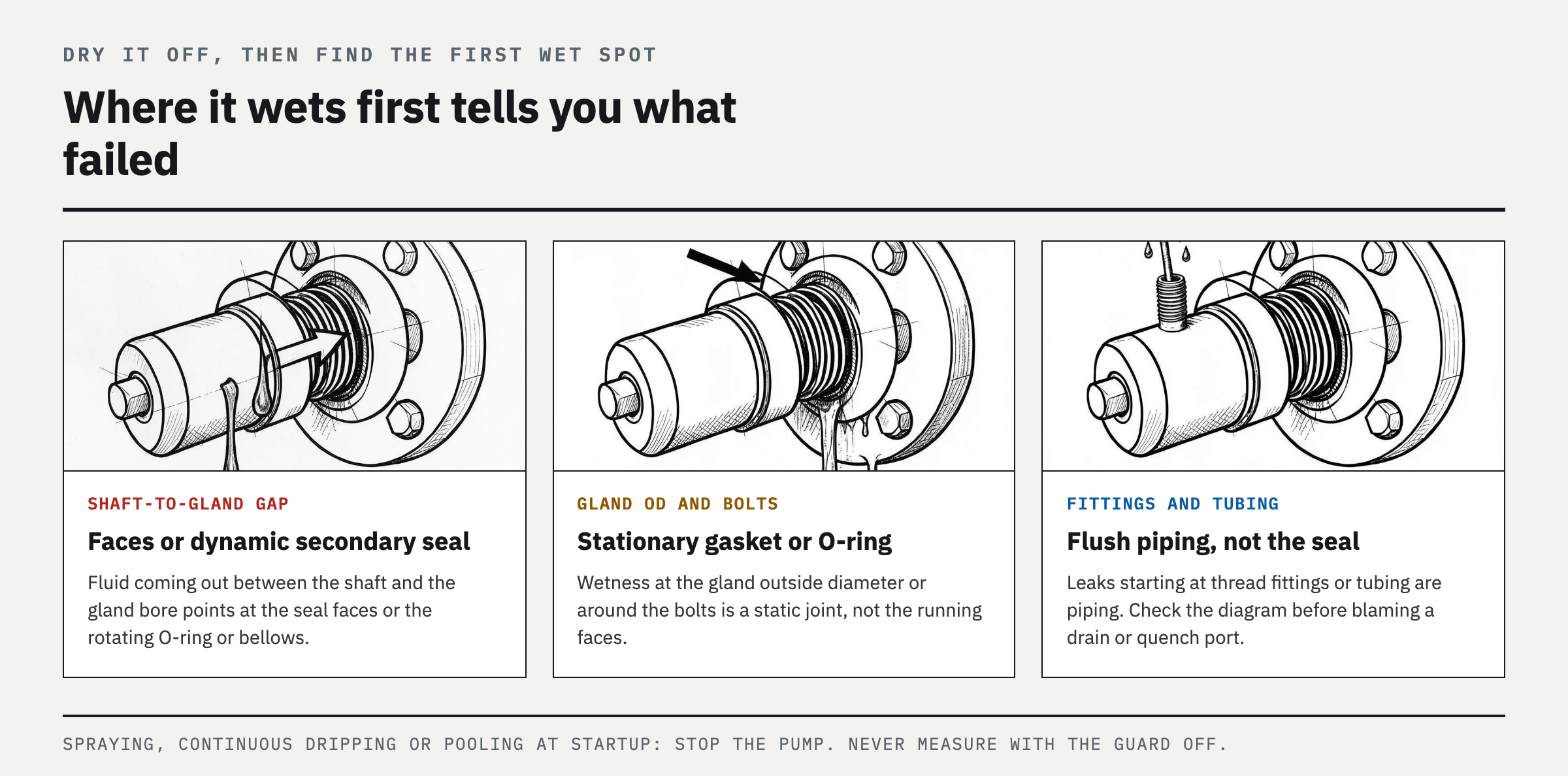
Clean and completely dry the area, then use a flashlight to locate the first point that becomes wet. Process fluid emerging between the shaft and gland points to the seal faces or a dynamic secondary seal. Leakage at the gland outside diameter or around the bolts points to a stationary gasket or O-ring. Leakage that starts at fitting threads or tubing points to the flush piping. Compare the piping diagram before mistaking liquid from a drain or quench port for seal leakage.
Stop the pump immediately if spraying, continuous dripping, or pooling begins at startup, or if heat, smoke, squealing, or vibration increases above normal. Never approach with the guard removed to measure leakage, and never touch a rotating gland with your hand or a tissue. On a dual seal, changes in barrier-system pressure, level, or flow can indicate an inboard seal failure even when there is no external leakage.
Causes in Order of Likelihood
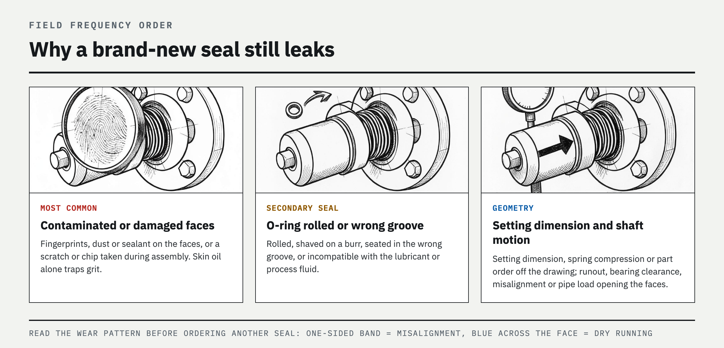
1) Fingerprints, dust, or sealant contaminated the faces, or the faces were scratched or chipped during assembly; 2) an O-ring or bellows rolled, entered the wrong groove, or is incompatible with the lubricant or process fluid; 3) the setting dimension, spring compression, direction of rotation, or component order differs from the installation drawing; 4) the sleeve or shaft has grooves, burrs, or corrosion, or the gland gasket surface is damaged; 5) shaft runout, bearing clearance, coupling misalignment, or pipe load opens the seal faces; 6) a closed flush valve, blocked line, air pocket, or unprimed pump interrupts cooling and lubrication; or 7) the seal materials or design are unsuitable for the actual pressure, temperature, solids content, or direction of rotation.
In the field, preserving the wear pattern on the removed seal is often faster than immediately ordering another new part. A polished band or heat discoloration concentrated on one side suggests misalignment, runout, or pipe load. Blue discoloration or cracking across the entire face suggests dry running or inadequate cooling. A shaved O-ring likely crossed a burr during assembly. These marks do not prove the cause; they help set the order of measurements.
How to Diagnose Each Cause
After disassembly, check for contamination and damage by shining a strong light across the faces at a low angle. Look for breaks in the contact band, chips, and radial scratches. Do not rub a seal face with your fingers. On O-rings, look beyond flattening and check for twisting, cuts, swelling, displacement from the groove, and whether the assembly lubricant was approved by the manufacturer. Recheck the setting dimension from the datum specified in the installation drawing for that model, not from memory or the pre-disassembly position. For cartridge seals, verify when the setting clips were removed and the sequence used to tighten the drive screws.
Clean the shaft and sleeve, then inspect the contact area for burrs and grooves. Measure runout, axial movement, and bearing clearance with a dial indicator at the locations and by the methods specified by the pump and seal manufacturers. Do not accept the equipment based on an arbitrary universal tolerance. Recheck coupling alignment with operating-temperature compensation. If the pump nozzle moves when the pipe bolts are loosened, pipe strain is being transferred to the pump.
Compare the flush or barrier system with the piping diagram and API Plan number. Verify supply and return direction, open valves, clogged filters or orifices, and kinked hoses. The seal chamber must fill with liquid and have a vent path that releases air from the high point. John Crane instructs that the seal-chamber lines for a liquid-service seal must be open and unobstructed and that the chamber must be vented and filled. If squealing or rapid overheating occurred, assume possible face damage and inspect the faces even if the pump ran only briefly.
Corrective Procedure

Mark the leak path and take photographs, then isolate electrical, pressure, thermal, and gravitational energy under the equipment-specific LOTO procedure. Isolate the suction, discharge, and auxiliary systems. Drain and vent the equipment, then verify zero pressure, a safe temperature, and removal of hazardous fluid. Record component orientation and damage patterns while disassembling the seal.
Remove burrs, corrosion, grooves, and gasket residue. If the shaft, sleeve, or gland datum surface is outside the manufacturer's limits, repair or replace it rather than hiding the damage by polishing. Correct bearing, runout, alignment, pipe-load, and flush problems first. Do not reuse damaged faces, O-rings, or gaskets; replace them with new components of compatible materials.
Follow the installation drawing exactly for orientation, reference dimensions, and tightening sequence, and keep the seal faces clean and dry. Use only a minimal amount of manufacturer-approved lubricant on O-rings. Open the flush valve, completely fill and vent the seal chamber and pump, then restore the guard and piping. Following the site commissioning procedure, briefly start the pump while observing from a safe distance. Monitor leakage, pressure, temperature, and vibration, and stop immediately if anything is abnormal. Apply LOTO again before any further disassembly.
Prevent Recurrence
Before work begins, use a one-page checklist to verify the installation drawing, BOM, seal model and materials, direction of rotation, and API Plan. Photograph the shaft position and piping condition before disassembly, but do not copy the previous setting dimension as if it were correct. Provide a clean work surface dedicated to seal faces and open the packaging only immediately before assembly. A process that prevents contamination of new faces reduces rework more reliably than cleaning a face after it has been touched.
Before commissioning, have the technician and operator cross-check that the pump is filled and vented, flush or barrier valves are open, setting clips have been handled correctly, and the coupling and guard have been restored. Record more than the leakage: include startup time, process pressure and temperature, flush status, vibration trend, and the first wet point. If leakage recurs at the same location, stop repeatedly replacing the seal and begin root-cause analysis of the shaft train and operating conditions.
FAQ
Why is my new mechanical seal still leaking?
The most common categories are contaminated or damaged seal faces, a rolled O-ring, an incorrect setting dimension or assembly sequence, shaft runout, misalignment, pipe load, a blocked flush, or an unprimed pump. First identify where the leak starts, then apply LOTO and compare disassembly marks and dimensions with the drawing. Simply replacing the seal again leaves shaft-train or operating causes in place and allows the leak to recur.
Does a new mechanical seal need time to bed in?
The manufacturer may specify an initial stabilization period or allowable leakage, but spraying, continuous pooling, overheating, or abnormal noise must never be treated as normal break-in while operation continues. Check the applicable seal IOM. If it gives no acceptance criterion or the leakage increases, stop the pump and inspect the installation and operating conditions.
Can you reuse a mechanical seal that leaked after installation?
Do not reuse a seal if its faces are scratched, chipped, or heat-discolored, or if an O-ring is cut, swollen, or permanently deformed. Appearance alone cannot verify face flatness or the absence of heat damage. Unless the manufacturer permits inspection and refurbishment of that seal design, installing new sealing components is the safer practice.
References
- John Crane, 8648VRS Seal Installation, Operation & Maintenance Instructions, April 2020
- Flowserve, 682R Reservoir API 682 Compliant Reservoirs User Instructions, SSIOM000743-01, April 2024
- OSHA, Control of Hazardous Energy (Lockout/Tagout), 29 CFR 1910.147
- OSHA, Lockout/Tagout eTool—Energy Control Program
- API Standard 682, Pumps—Shaft Sealing Systems for Centrifugal and Rotary Pumps
Spotted an error or have a question about this guide? Email contact@fixtheplant.com — corrections are prioritized.